Fixed Vertical Monopoles · Volume 5
DIY Build, Commercial Buys & Deployment
A complete 20 m elevated ground-plane build with real part numbers — including the sloping-radial trick that hands you a direct 50 Ω match — the NanoVNA workflow that tunes it, a ranked and dated commercial-buy survey across every vertical family this dive covers, the companion gear the radial field depends on, and the gotchas that catch first-time vertical builders
5.1 About this volume
The first four volumes of this dive built the fixed vertical from first principles and left it, deliberately, as an electrical abstraction: a monopole over an image plane with a 36 Ω feedpoint and 5.15 dBi of theoretical gain (Vol 1), a low-angle pattern whose real-world payoff depends entirely on a radial system that ranges from a bare-ground liability to a sixty-radial or four-elevated-radial asset (Vol 2), the commercial trap-vertical market that trades some of that ideal performance for band coverage on a single feedpoint (Vol 3), and the shortened and loaded variants that trade physical height for efficiency, plus the decision framework and power-handling realities that go with all of it (Vol 4). This volume is where that theory lands on a spool of aluminum tubing, a handful of radial wires, and a NanoVNA. It closes the dive the same way the companion Single-Band Dipoles dive closes its own five-volume arc: a complete DIY build with real, verified part numbers; a ranked, dated commercial-buy survey; the companion gear every fixed vertical depends on; and the myths that cost a season of degraded DX performance.
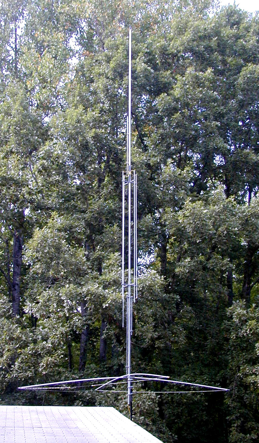
The DIY build is a 20 m elevated quarter-wave ground-plane — the vertical family’s answer to the dipole dive’s 40 m half-wave: legal-limit capable, mechanically modest, and free of the one thing that scares most first-time vertical builders away, a buried radial field. Vol 2 §7 already established why four elevated radials can match or beat sixty buried ones; this volume turns that result into a shopping list and a construction sequence, and adds a detail none of the first four volumes needed to cover: sloping those four radials downward from horizontal reshapes the feedpoint impedance, and at the right angle it hands you a clean 50 Ω match with no unun, no gamma match, and none of the matching hardware Vol 1 §8 catalogued. Section 4’s NanoVNA workflow accordingly has two independent knobs to turn, not one — length sets the resonant frequency, and radial droop angle sets how close the resistive part lands to 50 Ω — where the dipole dive’s equivalent section only ever had one.
Section 5 is the commercial-buy survey, ranked across the same price tiers the rest of this hub uses and checked against live vendor pages as of early July 2026. It spans every fixed-vertical family this dive has covered: trap multiband verticals (Hustler), a no-radials elevated-feed design (GAP), no-radials trap designs (Cushcraft), and a compact stealth-format vertical (MFJ) — with an honest note on which of those are actually orderable new today, because two of them are not. Sections 6 and 7 round out the practical picture — companion gear and the gotchas that recur across fixed-vertical installations generally — and Section 8 closes the whole dive.
One housekeeping note before the parts list, carried forward from every DIY volume in this hub: every price, part number, and product below was checked against a live vendor page, manufacturer datasheet, or manufacturer’s own online store as of early July 2026, and is marked accordingly. Where a specific number could not be confirmed — because a listing shows no current price, or a product shows as unavailable at every dealer checked — that is stated explicitly, with the best available reference point, rather than invented. A hedged approximate figure beats a fabricated precise one.
5.2 DIY build — the bill of materials
This is the elevated-ground-plane build the migrated seed material for this dive first sketched, carried forward and re-verified against current vendor listings: a resonant 20 m quarter-wave vertical, self-supporting telescoping aluminum tubing, fed through a radial plate with four sloping elevated radials, no buried ground system required. Budget an afternoon of bench and installation work plus the sweep-and-trim loop of Section 4.
The worked example below is dimensioned for 14.175 MHz, mid-band in the General/Advanced/Extra phone sub-band; rescale every length linearly from Vol 1 §3’s 234/f_MHz relation for a different design frequency.
Table 1 — 2. DIY build — the bill of materials
| Part | Specification | Source (verified) | Price (early July 2026) |
|---|---|---|---|
| Radiator, bottom section | 1.000 in. OD, 6 ft, 6063-T832, 0.058 in. wall, no-slit | DX Engineering DXE-AT1484 — verified live listing | $24.99 |
| Radiator, middle section | 0.875 in. OD, 6 ft, 6063-T832, 0.058 in. wall, one end slit (telescopes into the bottom section) | DX Engineering DXE-AT1208 — verified live listing | $31.99 |
| Radiator, top section | 0.750 in. OD, 6 ft, 6063-T832, 0.058 in. wall, no-slit (telescopes into the middle section) | DX Engineering DXE-AT1482 — verified live listing | $19.49 |
| Radial wire (4×) | 14 AWG, 19×27 stranded copper, UV-resistant black PVC jacket, 150 ft spool — far more than the ~72 ft four radials need, with slack for a second build | DX Engineering DXE-ANTW-150 — verified live listing | $49.99 |
| Radial plate / feedpoint | 304 stainless, 1/8 in., 11.625 in. sq., 60 laser-drilled radial-attachment holes, laser-cut SO-239 bulkhead cutout, fits up to 3 in. OD pipe | DX Engineering DXE-RADP-3 — verified live listing | $99.99 |
| Radial plate hardware kit | 20 sets of 1/4-20 stainless bolts, nuts, flat/split/star washers | DX Engineering DXE-RADP-1HWK — verified live listing | $11.59 |
| SO-239 bulkhead connector | Standard UHF female chassis/bulkhead jack; no single canonical SKU — any quality Amphenol-pattern part fits the DXE-RADP-3’s cutout | Generic — widely stocked | ≈ $8–12 |
| Support stub | Schedule 40 PVC pipe, 2 in. nominal (2.375 in. OD — within the radial plate’s 3 in. clamp range), ~1.5–2 m cut, plus a cap and ground-set fitting | Generic — any hardware store | ≈ $15–25 |
| Halyard / light guy | 3/16 in. double-braided Dacron/polyester, 770 lb break strength, UV-stabilized, 500 ft spool | DX Engineering / Synthetic Textile Industries SYN-DBR-187-500 — verified live listing | $85.99 (a 30–50 ft cut is all this build needs; DXE rates this line for antenna support, not tower guying) |
| Coax pigtail | RG-8X, PL-259 to the radial plate’s SO-239, ~1–3 m | Generic — any quality RG-8X with crimp or solder PL-259s | ≈ $12–20 |
| NanoVNA | 10 kHz–1.5 GHz+, 4 in. touchscreen, SMA OSL calibration kit, USB-C | Nooelec NanoVNA-H4 — verified on manufacturer site | $124.95 (one-time tool cost, not consumed per build) |
| Ground stakes (4×) | 12–18 in. galvanized or stainless tent/rebar stakes, for radial-tip tension | Generic — any hardware store | ≈ $8–12 |
| Weatherproofing | Self-amalgamating rubber tape + vinyl overwrap | 3M Scotch 130C + 3M Super 33+ — both standard, widely stocked | ≈ $15 combined |
Reading the table. The three telescoping tubing sections are the build’s single largest line item — $76.47 total for 18 ft of raw stock that assembles, with roughly a foot of overlap at each of the two joints, into a self-supporting ~17 ft radiator with a hacksaw-trimmable top few inches. DX Engineering also sells a pre-clamped 65 ft telescoping kit (DXE-ATK65A, twelve sections from 2.0 in. down to 7/8 in. OD, stainless clamps included, $499.99 verified) that is the better buy if you’re building more than one vertical or want a taller multi-band mast — but for a single 20 m element, three individual sections plus a set of stainless hose clamps at the joints is the more sensible one-antenna purchase, mirroring the “buy just enough, not the bulk kit” logic this hub’s DIY sections apply throughout. A budget-tier alternative that swaps the drawn 6063-T832 stock for generic 6061-T6 tubing from a metals supplier such as OnlineMetals.com in the same three diameters typically prices $15–20 lower per section — real, buildable, but without a single canonical SKU worth citing here.
The radial plate is the second cost fork. $111.58 for the DXE-RADP-3 plus its hardware kit buys a code-clean, laser-drilled, 60-hole stainless plate that has room to grow — this build uses four of its sixty holes, and the spare capacity is exactly the upgrade path Section 7 discusses if you later want to add elevated radials beyond the classic four. A homebrew alternative — a corrosion-resistant aluminum or brass disc, a panel-mount SO-239, and a handful of stainless hose-clamped lugs for the radial ends — does the same job for roughly $25–35 in generic hardware, at the cost of drilling your own holes and living without the DX Engineering installation guide. Both are legitimate; this is the same commercial-vs-DIY-hardware fork the Single-Band Dipoles dive’s balun section works through for its 1:1 choke.
Total for the table as written: roughly $238 in DX Engineering-branded hardware (the three tubing sections at $76.47, the radial wire spool at $49.99, and the radial plate plus its hardware kit at $111.58) plus $58–84 in generic hardware-store items (the SO-239, the PVC stub, a short coax pigtail, ground stakes, and weatherproofing tape) — call it roughly $295–325 for a fully premium build. Substituting generic-supplier aluminum tubing for the three DX Engineering sections and a homebrew radial bus for the DXE-RADP-3 and its hardware kit brings that down to roughly $150–195. Both figures exclude the NanoVNA (a reusable tool, not a per-build consumable) and price the halyard rope as a short cut rather than the full 500 ft spool.
5.3 DIY build — construction and the sloping-radial trick
Cut the radiator sections and dry-fit them long. Vol 1 §3’s 234/f_MHz relation gives 16.51 ft (5.03 m) as the trimmed resonant target at 14.175 MHz. Assemble the three telescoping sections with roughly 5–6 in. of overlap at each joint — enough for a secure stainless hose-clamp bite on a radiator this light — so that from three 6 ft sections (18 ft of stock, less ~1 ft to the two joints) the stack comes in right around 17 ft, comfortably on the “cut long” side of the target the same way this hub’s wire builds are always cut long: a hacksaw only ever makes tubing shorter, and the few inches of headroom at the top section’s tip is exactly what Section 4’s sweep-and-trim loop consumes.
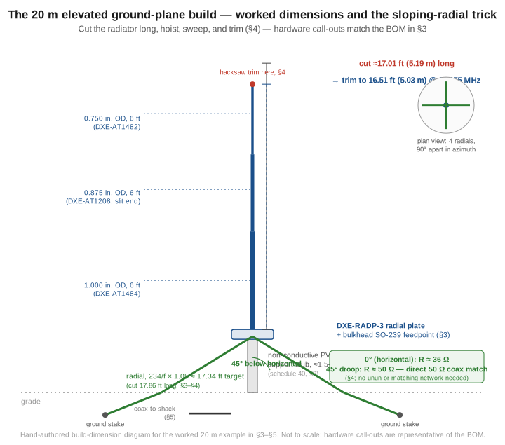
Mount the radial plate. Clamp the DXE-RADP-3 (or the homebrew equivalent) to the top of the PVC support stub using its built-in V-bolt bracket, with the stub’s other end set roughly 1.5–2 m into the ground or a post-mount fitting — high enough that the radials, once drooped, clear grass and casual foot traffic at their low point. The support stub must be non-conductive. A metal mast here would bond to the radial-plate common point and become an unintended, un-tuned part of the ground system exactly as Vol 4 §4’s discussion of the radial system as a return-current conductor would predict — schedule 40 PVC sidesteps the question entirely rather than requiring an insulated standoff partway up a metal support.
Install the SO-239 and bond the radiator. Bolt the generic SO-239 bulkhead connector into the plate’s laser-cut cutout, center pin toward the radiator side. Slide the assembled tubing stack into the plate’s clamp bracket directly above the SO-239’s center pin and bond the bottom section to the connector’s center conductor with a short, low-inductance strap — this is the antenna’s one true current-maximum point, the same standing-wave logic Vol 1 §4 established for the theoretical case, and it wants a low-resistance, mechanically solid bond, not a convenient afterthought.
Attach and route the four radials. Cut each radial 3% over a 17.34 ft (5.28 m) target — 234/f_MHz scaled by the widely followed rule of making elevated radials roughly 5% longer than the radiator, per the ARRL Antenna Book and ON4UN’s Low-Band DXing — for a cut length of about 17.86 ft (5.44 m) each. Bolt all four to the plate’s common bus, spaced 90° apart in azimuth, and run each one outward to a ground stake at whatever droop angle the next paragraph calls for.
The sloping-radial trick. A quarter-wave vertical over an ideal ground image plane presents roughly 36 Ω at its feedpoint — the figure Vol 1 §5 derived from the image-plane picture. Four horizontal elevated radials approximate that same low-30s-to-36 Ω resistance reasonably well, because a horizontal radial contributes essentially no radiation of its own and functions as a near-ideal counterpoise — but 36 Ω on 50 Ω coax is a real, if modest, mismatch (SWR ≈ 1.39:1, Vol 1 §7). Drooping the four radials downward, toward roughly 45° below horizontal, raises the feedpoint resistance toward 50 Ω — a well-documented, physically real effect (not a myth Section 7 needs to debunk) that several independent antenna references derive and confirm: sloping the radials couples them into the radiating system in a way flat radials do not, and the feedpoint impedance climbs smoothly with droop angle from the horizontal-radial value toward, and somewhat past, 50 Ω as the slope steepens toward vertical. 45° is the practical sweet spot — steep enough to land close to 50 Ω, shallow enough that the radial tips still clear the ground by a useful margin and the radial system still behaves like a counterpoise rather than four more quarter-wave verticals wired in parallel with the main element. The payoff is real and worth stating plainly: this build needs no unun, no gamma match, no L-network — Vol 1 §8’s entire matching-options catalogue is sidestepped by a mechanical adjustment to four wires, which is about as good a trade as antenna engineering offers.
Guy the top section lightly. At 17 ft of thin-wall aluminum tapering to 0.75 in. OD at the tip, the radiator is self-supporting in still air but benefits from one or two light guy lines of the halyard rope, tied off a few feet below the top and anchored at roughly 120° spacing, to damp wind flex on gusty days — a nod to the same halyard-and-counterweight logic the dipole dive’s companion-gear section develops for wire spans, applied here to a rigid element instead.
Weatherproof the connector. Once the SO-239-to-coax joint is made up, wrap it in 3M Scotch 130C self-amalgamating tape followed by a 3M Super 33+ vinyl overwrap — the same two-layer treatment (rubber tape for the seal, vinyl for UV protection) this hub’s other DIY volumes specify, because one layer alone reliably fails at one of those two jobs within a season.
5.4 Tuning with a NanoVNA — two knobs, not one
Calibrate at the feedpoint, every time. Run the standard OSL (Open-Short-Load) sequence — Open, then Short, then Load, then Done, saved to a calibration slot — with the calibration plane set at the radial plate’s SO-239 itself if you can reach it, or at the shack end of a known feedline if you can’t, in which case remember the feedline’s own length and loss are now baked into every reading that follows. A Smith-chart sanity check (open at the far right edge, short at the far left, load dead center) confirms the calibration is good before touching the antenna.
The first sweep has two things wrong with it, not one. Unlike the dipole dive’s tuning loop — where a cut-long wire is only off in frequency — this build’s very first sweep, taken with the radiator at its as-assembled length and the radials still lying flat and horizontal from the initial hoist, is wrong in both frequency and impedance: the resonant dip sits below 14.175 MHz because the tubing is intentionally cut long, and even once you find that dip its floor sits well short of a deep null because the horizontal radials are presenting something close to Vol 1 §5’s 36 Ω figure into a 50 Ω line rather than the 50 Ω the drooped configuration targets.
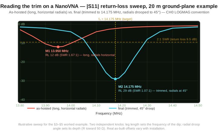
Fix the frequency first, with the radials still horizontal. Read where the sweep’s minimum actually sits — if it’s below 14.175 MHz, the radiator is electrically too long (expected, since it was cut that way on purpose) and needs shortening at the top section’s tip; if it somehow sits above target, double-check the assembly before assuming the tubing itself is at fault. Lower the radiator, trim a small amount off the top section with a hacksaw — Vol 1 §3’s length-frequency relation is close enough to linear over a few percent that a rough proportional estimate (how far off in kHz, scaled by how many kHz per cm of trim) gets you there in two or three iterations — re-assemble, re-hoist, and re-sweep. Leave the radials horizontal through this whole loop; changing droop angle and length at the same time just makes both adjustments harder to read.
Then fix the impedance, by adjusting droop angle, with the length now fixed. Once the sweep’s minimum sits within a few kHz of 14.175 MHz, start lowering the radials from horizontal toward 45°, watching the return-loss floor deepen as you go (equivalently, the Smith-chart trace should be visibly shrinking toward the center of the chart rather than sitting off to one side on the real axis). Stop somewhere in the neighborhood of a 25–30 dB null — chasing the absolute deepest possible number on a real installation, with real ground and real wire tolerances underneath the idealized 45°/50 Ω figure, usually costs more fiddling than the last couple of dB are worth. A small secondary frequency shift typically accompanies the droop adjustment (drooping radials changes their own effective length slightly, which couples back into the system resonance); a final light trim after settling on a droop angle is normal and not a sign anything went wrong.
What a good final sweep looks like. At minimum: an SWR floor at or below roughly 1.2:1 (a well-executed 45°-droop match commonly lands closer to 1.05–1.15:1); the minimum within about 10 kHz of 14.175 MHz; a Smith-chart marker sitting close to the real axis with the reactance near zero; and — the fingerprint of a properly bonded feedpoint — no shift in the reading when you flex the coax a meter or two below the radial plate. A sweep that moves when the feedline moves means common-mode current is riding the shield, which Vol 2’s ground-loss discussion and this hub’s BALUN volume both treat as a choke problem to fix, not a length or droop-angle problem to trim around; a 1:1 current choke at the feedpoint (Section 6) is the standard cure.
5.5 Commercial buys — ranked, with price tiers
For the builder who would rather buy a factory-tuned reference than spend an afternoon with a hacksaw, the following are current amateur HF vertical products spanning every fixed-vertical family this dive covers, checked against live manufacturer or authorized-dealer listings as of early July 2026. Two of the six show as unavailable at every dealer checked — a real, worth-knowing fact about the current commercial vertical market, not an omission on this volume’s part.
Table 2 — 5. Commercial buys — ranked, with price tiers
| Tier | Product | Bands | Price (early July 2026) | Notes |
|---|---|---|---|---|
| Budget | Hustler 4-BTV | 10/15/20/40 m (75/80 m via add-on) | $369.98 (verified, DX Engineering) | 21.5 ft trap vertical, 1,500 W SSB/1,000 W CW, 52 Ω nominal, non-tilt aluminum bracket. The classic entry-level multiband trap vertical — Vol 3’s technical reference case — and it needs a real radial system to perform; DX Engineering’s own listing says so directly. |
| Budget-mid | Hustler 5-BTV | 10/15/20/40/75-or-80 m | $459.98 (verified, DX Engineering) | 25.1 ft, same trap-vertical family, five bands via internal traps and an add-on for the low-band option. |
| Mid | Hustler 6-BTV | 10/15/20/30/40/75-or-80 m | $499.98 (verified, DX Engineering) | 24 ft, the most-installed amateur HF vertical by a wide margin; 1.25 in. heavy-wall aluminum sections, fiberglass trap forms, radials required for rated performance and not included — budget separately per Section 6. |
| Mid | GAP Titan DX | 10/12/15/17/20/30/40 m + partial 80 m | $589.95 (verified, gapantenna.com) | 25 ft, 25 lb, double-wall tubing, center-fed with four rigid 80 in. counterpoises rather than a grounded quarter-wave — a fundamentally different, genuinely no-radials matching topology (not a lossy-lie no-radials claim; Section 7 draws that distinction explicitly). No published amateur power rating on the current datasheet; user reports at legal limit are common but not a manufacturer spec. |
| Premium | Cushcraft R-8 | 6/10/12/15/17/20/30/40 m | $699.95 (verified, sold via MFJ’s legacy storefront — Cushcraft/Hy-Gain were bought out of the MFJ estate by ITU Corporation in April 2026, per Vol 3, and the transition is ongoing) — shown out-of-stock/unavailable at every dealer checked, including MFJ’s own site, as of early July 2026 | 28.5 ft, no radials required by design, 1,500 W, rated to sustain a 3:1 mismatch at full power for use with a tuner. A genuine “no radials” no-ground-system vertical, distinct from the loaded-loss designs Section 7 warns against — but effectively not available new right now; the used market is the practical path to one. |
| Premium | Cushcraft R-9 | 6/10/12/15/17/20/30/40/80 m | $799.95 (verified, MFJ Enterprises’ own store) — also shown unavailable as of early July 2026 | 31.5 ft, no RF ground or radial network required; power derates to 750 W CW / 500 W RTTY-PSK even though PEP is rated 1,500 W — a real, specific derate worth knowing before assuming “1,500 W” covers every mode. |
| Specialty (stealth) | MFJ-1796 | 40/20/15/10/6/2 m | $369.95 (verified, MFJ Enterprises’ own store) — shown unavailable as of early July 2026 | 12 ft, ground-independent half-wave vertical, capacitive hat plus inductive end-loading on fiberglass forms achieves a 50 Ω match with no radials and no RF ground of any kind, 1.125 in. aluminum radiators, fully automatic band selection. The compact, restricted-space answer in this table — a genuine alternative to this volume’s ground-plane build for a lot with no room for a radial field at all. |
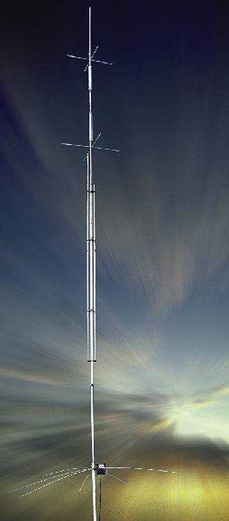
What to avoid. “No radials needed” claims with no stated matching topology behind them — a vertical that hits 50 Ω without radials by being lossy enough that a built-in matching network absorbs the mismatch is exactly the trap Section 7 names, and neither the GAP’s rigid-counterpoise design nor the Cushcraft R-series’ documented no-ground topology is that trap, but a nameless import listing making the same claim with no explanation deserves real skepticism. A trap vertical (Hustler, and the multiband trap designs Vol 3 surveys in depth) advertised without mentioning that radials are needed for rated performance is a listing quietly omitting the one thing that determines whether the antenna is a DX performer or a noise-bucket, per Vol 2’s efficiency numbers. And — the market-condition note this table makes concrete — three of the six products above are effectively hard to buy new as of mid-2026 (Cushcraft R-8, R-9, and the MFJ-1796 all show unavailable at their own manufacturer’s store); the used market for Hustler BTVs and any Cushcraft R-series unit that turns up is genuinely strong, because traps and cap-hat hardware from these designs routinely outlast a first owner’s station.
5.6 Companion gear — the radial field, mounting, feedline
A fixed vertical is a system, and for the ground-mounted trap verticals in Section 5’s table the radial field is most of that system.
Buried radial wire. For a Hustler BTV or any ground-mounted trap vertical, Vol 2 §6 already quantified the diminishing-returns curve — the jump from a bare-ground installation to a real radial field is worth several dB, and the jump from 16 to 60-plus radials is worth a fraction of a dB more. DX Engineering’s premium bulk radial wire — DXE-RADW-500 (500 ft, verified, $139.99) or DXE-RADW-1000 (1,000 ft, verified, $260.99) — is the raw-stock path; a pre-terminated option like DXE-RADW-32RT (20 radials, 32 ft each, 14 AWG, crimped-and-soldered ring terminals, verified, $345.99) trades a higher per-foot price for no field-terminating labor. A radial plate or bus — this volume’s own DXE-RADP-3, or the equivalent for a ground-mounted feedpoint — is the common bonding point every radial converges on; Vol 4 §4’s discussion of the radial system as a current-carrying return conductor applies with full force here, and a corroded or crimped-only bond at that common point is the single most avoidable loss mechanism in the whole system.
Elevated radial wire. For this volume’s own DIY build, or for a GAP or Cushcraft-style no-radials design’s counterpoise hardware, the same DXE-ANTW-150 insulated stock this volume’s BOM uses is the natural choice — UV-jacketed, easy to route without snagging on grass or foot traffic, and forgiving of the modest tension a 45°-droop elevated radial actually sees.
Mounting. A ground-mounted trap vertical needs a non-conductive base insulator so the radial system, not the mounting hardware, is the RF ground reference — the same principle Section 3 applies to this volume’s PVC support stub, just at ground level instead of 1.5–2 m up. A tilt-base mount (DX Engineering and most manufacturers sell one matched to each specific model) turns a multi-hour install-and-tune cycle into a five-minute one for routine maintenance and seasonal band-plan changes.
Feedline. RG-8X is adequate for short runs under roughly 25 m at legal-limit power, with the vertical’s mild 36–50 Ω-range mismatch costing negligible additional loss on top of the coax’s own matched-line figure; longer runs move to LMR-400-class cable or hardline, the same tradeoff Transmission Lines & Feedlines works out in full.
Common-mode choke. A 1:1 current choke at the feedpoint — an FT240-31 toroid with a dozen turns of coax or hookup wire, or a commercial equivalent — is more important on an elevated ground-plane than on a ground-mounted one, because an elevated system’s coax has a clearer, less-grounded path back down to the shack for common-mode current to ride; the full winding theory and mix selection lives in this hub’s dedicated BALUN and UNUN volume ↗.
Lightning protection. A polyphaser-style arrestor at the feedline’s building entry, bonded to a single-point station ground, is standard practice for any permanent outdoor vertical — and verticals are, if anything, more attractive to a strike than a horizontal wire antenna, being vertical conductors against ground by construction. The full single-point-ground topology and arrestor selection belongs to this hub’s grounding and lightning-protection volume ↗, cited here rather than reproduced.
5.7 Gotchas and myths
“No radials needed” is either a genuine engineering claim or a marketing half-truth, and Section 5’s table draws the line explicitly: the GAP Titan DX’s rigid counterpoise and the Cushcraft R-series’ documented no-ground topology are real no-radials designs with a stated matching mechanism behind the claim, while an unbranded listing making the same claim with no explanation is very often burning power in a lossy internal matching network instead of radiating it — the SWR looks fine, the efficiency does not.
“Four elevated radials is the whole story” undersells N6LF’s (Rudy Severns) own later refinement of the result this volume’s build leans on. The original NEC modeling behind “four elevated quarter-wave radials perform as well as sixty-plus buried ones” holds up reasonably well, but Severns’ subsequent field measurements — published across his QEX “Ground System Performance for HF Verticals” series and collected at antennasbyn6lf.com — led him to recommend 10–12 or more elevated radials for verified best performance, particularly as radial height above ground and consistency between radials turn out to matter more than the simplest four-radial folklore suggests. The four-radial design in this volume’s BOM is the classic minimum-viable configuration and a genuinely good DX antenna — not a compromised one — but it is the floor of the elevated-radial performance curve, not its ceiling; the DXE-RADP-3’s spare 56 holes are exactly the upgrade path if you want to chase the last measure of Severns’ improvement later.
“My SWR is 1.3:1, so the antenna is working” is Vol 2 §9’s low-SWR trap restated for this volume’s build specifically: a poorly bonded radial system, or too few radials over lossy soil, can present a feedpoint resistance that happens to look acceptable on a 50 Ω line even though most of that resistance is ground loss rather than radiation resistance. The SWR reading alone cannot distinguish the two; a field-strength comparison against a known-good reference antenna, or simply trusting the quantified numbers Vol 2 already worked out for radial count versus loss, is the only way to know which case you’re in.
“Sloping the radials is a trick, so it must be a compromise” gets the physics backwards. The 45°-droop match Section 3 develops is not a workaround for a design flaw — it is the same physical mechanism (the radials coupling into the radiating structure) that a horizontal-radial ground-plane already relies on, just tuned by angle instead of accepted as a fixed 36 Ω. There is no efficiency penalty for choosing 45° over horizontal; the choice is a matching convenience, not a tradeoff.
Mounting near a metal roof, gutter, or downspout puts an unintentional, un-tuned parasitic conductor close to the radiating element and its radial field, and the result is rarely subtle: pattern distortion, an SWR curve that shifts every time it rains and the gutter’s grounding path changes, and — at worst — RF current induced onto the metal roofing itself, which is both an interference source and a personal-safety concern at legal-limit power. A vertical wants clear space in every direction its radials will occupy, not just clearance for the radiator itself; if the only available mounting point is close to structural metal, an elevated design with a well-defined counterpoise (this volume’s build, or a GAP-style rigid counterpoise) is more predictable than a ground-mounted trap vertical whose radial field has to route around the same obstruction.
“A vertical is omnidirectional, full stop” is the free-space idealization Vol 2 §4 already qualified — real installations near buildings, trees, or a sloping lot distort the azimuth pattern by a few dB in practice, and the theoretical circle is a starting point for site planning, not a guarantee.
5.8 Where this volume — and this dive — hands off
This volume closed the fixed-vertical-monopoles dive by putting the first four volumes’ theory on aluminum tubing and copper wire. It gave a complete, real-parts bill of materials and construction sequence for a 20 m elevated ground-plane — a verified $76.47 in telescoping tubing, a verified $111.58 radial plate and hardware kit, and the sloping-radial trick that turns Vol 1’s theoretical 36 Ω feedpoint into a direct 50 Ω match with no matching network at all. It formalized a NanoVNA workflow with two independent knobs — length for frequency, radial droop angle for impedance — where the dipole dive’s equivalent workflow only ever needed one. It surveyed the commercial alternative across every vertical family this dive covers, from a verified $369.98 Hustler 4-BTV through a verified $589.95 GAP Titan DX to two Cushcraft R-series verticals and a stealth-format MFJ design that are real, verified, and currently hard to actually buy new — an honest market snapshot rather than a tidy one. And it closed with the companion gear and the myths — the no-radials half-truth, the low-SWR ground-loss trap, N6LF’s own refinement of the four-radial folklore, and the metal-roof mounting hazard — that separate a fixed vertical that performs for a decade from one that quietly underperforms while reading fine on the meter.
Zooming out, this volume is also the last of the five that make up the fixed vertical monopoles dive. Vol 1 derived the image-plane theory — a monopole as half a dipole, the 234/f length rule, the 36 Ω feedpoint, and the matching options available when 36 Ω meets 50 Ω coax. Vol 2 took ownership of the radiation pattern and, more consequentially, the radial system — the low-angle DX advantage over real ground, the diminishing-returns curve from bare ground through sixty buried radials to four elevated ones, and the low-SWR trap that ground loss sets. Vol 3 surveyed the full-size HF trap-vertical market in technical depth. Vol 4 covered the shortened and loaded compromises a restricted height budget forces, a genuine decision framework across every vertical family, and the power-handling realities of insulators, loading coils, and the radial return path. And this volume put all of it on a bill of materials, a construction sequence, a NanoVNA workflow, and — for the reader who would rather buy than build — a dated shopping list.
The fixed vertical is this hub’s answer to low-angle DX and restricted-azimuth real estate, and the radial-system discipline this dive has carried from Vol 2 through this volume’s own BOM is the throughline: a vertical is only as good as what it works against. The matching-network theory this dive touched at its edges — the full BALUN/UNUN family beyond the single 1:1 current choke, and the antenna-tuner alternative to a resonant cut — lives in this hub’s dedicated matching-network dives ↗ ↗; the measurement theory behind the NanoVNA workflow Section 4 used lives in this hub’s measurement cluster ↗; and the physical-deployment concerns this volume touched only briefly — mounting and masts, weatherproofing, grounding and lightning — each have a full dedicated dive of their own ↗ ↗ ↗. The companion Portable & Mobile Monopoles dive picks up the vertical-antenna story where a permanent radial field is not an option at all ↗. This volume points to all of them rather than reproducing them, consistent with the whole hub’s cross-linking discipline.
5.9 Resources
- ARRL Antenna Book (25th+ ed.), the vertical-antenna and ground-system construction chapters — the canonical amateur reference for elevated and buried radial design, and the source for the “radials cut 5% longer than the radiator” convention Section 3 uses.
- ON4UN, Low-Band DXing (5th ed.) — the authoritative 80/160 m vertical and radial-system reference for serious DXers; cited in full in Vol 2.
- N6LF (Rudy Severns) — “Experimental Determination of Ground System Performance for HF Verticals” and the “Design of Radial Ground Systems” QEX series, collected at antennasbyn6lf.com — the field-measurement work behind Section 7’s refinement of the four-elevated-radials folklore.
- DX Engineering — https://www.dxengineering.com — the source verified for the tubing, radial-plate, radial-wire, and halyard-rope part numbers and prices in Sections 2 and 6, and the Hustler BTV series prices in Section 5.
- GAP Antenna Products — https://gapantenna.com — the source verified for the Titan DX specification, price, and product photography in Section 5.
- MFJ Enterprises — https://mfjenterprises.com — the source verified for the Cushcraft R-8, R-9, and MFJ-1796 current prices, availability status, and product photography in Section 5.
- practicalantennas.com, “Understanding the Quarter-Wave Ground Plane Antenna,” and L. B. Cebik’s (W4RNL) “On Ground Planes” (antentop.org) — the sources verified for the sloping-radial impedance-transformation effect Section 3 builds the DIY match around.
- Nooelec — https://www.nooelec.com — the source verified for the NanoVNA-H4 specification and price in Section 2, the same tool the sibling Single-Band Dipoles dive verified independently at the identical price point.
- NanoVNA-Saver (PC companion software) — https://github.com/NanoVNA-Saver/nanovna-saver — free, and the natural next step once Section 4’s on-device sweep confirms the two-knob tuning is converged; it logs and overlays sweeps, the easiest way to compare an as-hoisted and a final trace like the one in this volume’s figure.
- The hub’s dedicated matching-network dives (BALUNs & UNUNs, Antenna Tuners) — the full transmission-line-transformer theory and the tuner alternative to a resonant cut.
- The hub’s measurement cluster (NanoVNA deep dive, other analyzers, power/SWR measurement) — the full instrument-level treatment behind the workflow Section 4 used at the level this dive needed.
Comments (0)