Fixed Vertical Monopoles · Volume 3
Full-Size Verticals — HF Trap Verticals & the Half-Square
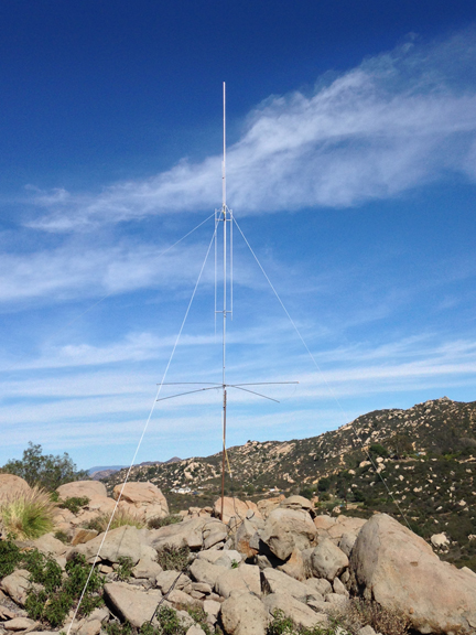
The Hustler 4-BTV/5-BTV/6-BTV, Cushcraft R-9/R-8, and GAP Titan DX product families and what each actually requires of its ground system, then the half-square — two quarter-wave verticals joined by a half-wave top wire for several dB more low-angle gain and no radial field at all
3.1 About this volume
Vol 1 built the quarter-wave monopole from first principles — the image-plane derivation that halves the dipole’s feedpoint impedance to a nominal 36 Ω, the standing-wave picture with current maximum at the base and voltage maximum at the top, and the length tables that follow directly from 234/f. Vol 2 took ownership of the part of the vertical that lives underground (or doesn’t): the radial field’s job as the low-loss substitute for a lossy earth image, the buried-versus-elevated tradeoff, and the radiation pattern and SWR behavior that result. Both volumes treated “the vertical” as a single generic quarter-wave radiator over some radial system, because that is the cleanest way to derive the physics.
Nobody buys a generic quarter-wave radiator. What a ham actually orders from DX Engineering, or builds by hand, is one of a small number of well-defined product families, and the families differ from each other in ways that matter a great deal to an installation — most importantly, in what each one actually requires of the ground beneath it. This volume covers two things that both answer the multiband-and-no-real-estate-for-more question: the commercial full-size HF trap vertical market (Hustler’s BTV line, Cushcraft’s R-Series, and GAP’s Titan DX — three genuinely different design philosophies wearing the same “multiband vertical” label), and the half-square, a wire antenna that trades the vertical’s omnidirectional pattern for several more dB of gain broadside to its plane, at the price of needing two supports instead of one and giving up the 360° coverage.
The throughline connecting both halves of this volume is the same question Vol 2 made central: where does the return current go, and what does the antenna cost you if you get that wrong? A trap vertical from Hustler is, electrically, exactly the animal Vol 1–Vol 2 described — a quarter-wave (multiplied by however many traps are active) monopole that needs a competent ground system underneath it, full stop, regardless of what the sales copy on a competing product implies. A Cushcraft R-Series antenna and a GAP Titan DX both market themselves as “no radials,” and both claims are true — but the two products get there by entirely different electrical mechanisms, and conflating them is a common and consequential mistake. The half-square sidesteps the ground question altogether by building its own return path out of real copper rather than earth image current. Getting each of these mechanisms right, not just the marketing headline, is this volume’s job.
3.2 Three designs, three ground-system answers
Before the model-by-model detail, it is worth stating the three design philosophies side by side, because the amateur market blurs them under a common “multiband vertical” umbrella and the blurring causes real confusion about what belongs where.
The trap monopole (Hustler 4-BTV/5-BTV/6-BTV) is the textbook animal: a single vertical conductor, electrically shortened band by band with series LC traps, fed at its base against a ground reference exactly as Vol 1 derived. It needs a radial field — buried or elevated — precisely as much as any other quarter-wave vertical does, and the manufacturer’s own installation literature says so explicitly. There is no trick here; the “multiband” part is entirely in the traps, and the ground-system requirement is unchanged from a single-band vertical.
The end-fed half-wave vertical (Cushcraft R-9/R-8, and their ancestor the R-7) is a genuinely different electrical structure. It is not a quarter-wave monopole with a clever matching network bolted on; it is a half-wave-plus radiator fed from one end through an internal transformer, with the current maximum sitting somewhere in the middle of the element rather than at the base. Because the feedpoint is not a current maximum against ground, the antenna does not need a low-loss return path for a large base current the way a monopole does — and Cushcraft’s own manual is emphatic that these antennas should not be connected to a ground radial system at all, since doing so changes the very electrical structure the internal matching network was tuned for.
The elevated-feed asymmetric vertical (GAP Titan DX) takes a third path entirely: it is trap-free, feeds the radiator partway up the structure rather than at the base, and supplies a small, physically built-in counterpoise (rigid rods, not a buried field) rather than relying on the earth at all. Section 5 develops why raising the feed point, specifically, is what eliminates the near-field ground-loss term that a base-fed vertical cannot avoid.
All three are legitimately marketed as solving the “I want multiband HF and I don’t have (or don’t want) a big radial field” problem, and all three actually do solve it — but “no radials” means something different in each case, and the distinction matters when you are troubleshooting one, comparing efficiency claims, or deciding which compromise fits your lot.
3.3 Hustler 4-BTV / 5-BTV / 6-BTV — the trap-vertical reference
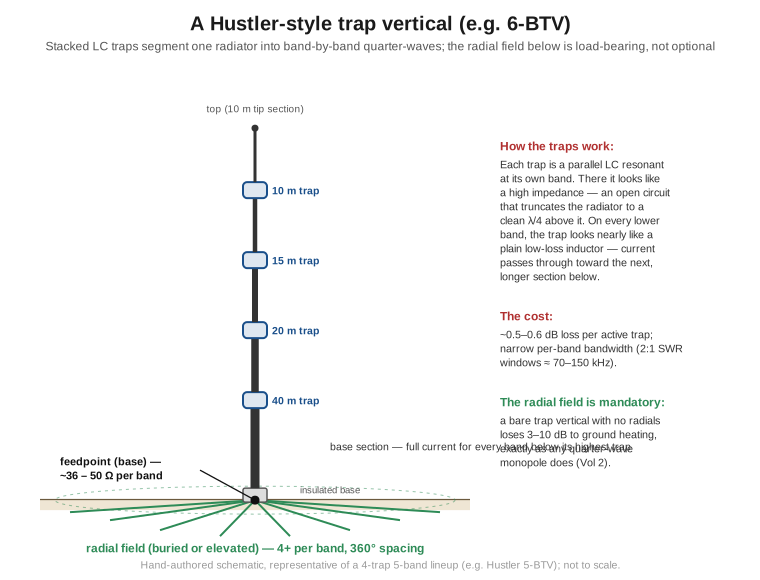
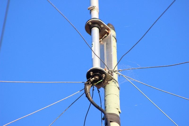
The New-Tronics/Hustler BTV series (now sold and supported through DX Engineering) is the most-installed multiband HF vertical family in amateur radio, and it earns that position by being the least mysterious of the three: a single aluminum-tubing radiator, segmented band-by-band with series-resonant LC traps exactly as a trap dipole is segmented — each trap presents a high impedance at its own design frequency, electrically truncating the radiator to a quarter-wave at that band while looking like a low-impedance pass-through (part of a longer conductor) to lower frequencies. The traps stack from the top down, shortest-wavelength band first, so each successive lower band sees the full accumulated length below it.
3.3.1 Model lineup and verified specifications
Table 1 — 3.1 Model lineup and verified specifications
| Model | Native bands | Height | Power | Price (mid-2026, DX Engineering) |
|---|---|---|---|---|
| Hustler 4-BTV | 10 / 15 / 20 / 40 m | 21.5 ft (6.6 m) | 1,500 W SSB / 1,000 W CW | $369.98 |
| Hustler 5-BTV | 10 / 15 / 20 / 40 / 75-80 m | ~25 ft (7.6 m) | 1,500 W SSB / 1,000 W CW | $459.98 |
| Hustler 6-BTV | 10 / 15 / 20 / 30 / 40 / 75-80 m | 24 ft (7.3 m) | 1,500 W SSB / 1,000 W CW | $499.98 |
Two corrections against older summaries of this line are worth calling out explicitly, because they are easy to get backward. First, 75/80 m is native to the 5-BTV and 6-BTV, not an add-on — the model-number step from 4 to 5 bands is the 75/80 m resonator, already built in. It is only the 4-BTV that lacks 80 m natively; DX Engineering sells a dedicated 80 Meter Add-On Kit (built around a Hustler RM-80 or RM-80S resonator) specifically to bring an existing 4-BTV up to 80 m coverage without disturbing its other bands. Second, 12 m and 17 m are not native to any stock BTV model — they are separate DX Engineering add-on kits (DXE-AOKC-12M and DXE-AOKB-17M/DXE-AOKC-17M) that clip onto an existing 4-, 5-, or 6-BTV and add full-band WARC coverage without affecting the bands already installed; the two kits are compatible with each other and can be fitted simultaneously. A 6-BTV with both WARC kits installed becomes an eight-band antenna, but that eight-band coverage is assembled from the base unit plus two aftermarket kits, not delivered out of the box.
3.3.2 Radial requirement — explicit, not optional
The BTV series is a conventional base-fed quarter-wave monopole on every band it covers, and Vol 2’s entire radial-field treatment applies to it without modification. DX Engineering’s own installation guidance for the line states the requirement plainly: install at minimum two insulated radial wires per band, with four resonant radials per band recommended for good low-angle performance, laid out evenly around the full 360° and — where elevated rather than buried — sloped downward at roughly 45° from horizontal. There is no internal matching trick that substitutes for this; skipping the radial field on a BTV produces exactly the ground-loss penalty Vol 2 quantified for any bare quarter-wave vertical (3–10 dB of efficiency lost to soil heating, with the loss dropping toward under 1 dB only once a real radial field — buried or elevated — is in place).
3.3.3 Trap loss and per-band bandwidth
Traps are not free. A well-designed trap in a quality vertical costs on the order of a few tenths of a dB on the bands where it is in the active current path — general trap-antenna literature puts the loss at roughly 0.5–0.6 dB relative to an equivalent trap-free length of the same wire, worse on the lowest band a trap serves (where the trap sits closest to the high-current base) and smaller on higher bands. Stacked traps compound this modestly band by band, which is why a 6-BTV’s lowest bands (40 m and especially 75/80 m, which sees every trap in the stack) run measurably less efficient than its highest (10 m, which the antenna covers with the shortest possible current path and no trap loss at all above the first). The other cost of trap loading is narrow per-band bandwidth — each trap-defined section behaves as its own resonant circuit, and a typical BTV band shows a 2:1-SWR bandwidth on the order of 70–150 kHz, tight enough on 40 m and the WARC-kit bands that a rig’s built-in tuner or a modest external tuner is common practice rather than an admission of a poor installation.
3.3.4 Strengths and weaknesses
The BTV line’s case for itself is simplicity and a three-decade service record: a self-supporting single tube, standard 1-1/2″-pipe base mounting, and a design that has not meaningfully changed since the 1970s because it did not need to. Its weaknesses are the direct consequence of the trap-and-radial-field approach: a competent radial system is mandatory, not optional; per-band bandwidth is the narrowest of the three families in this section; and the WARC bands cost extra hardware rather than arriving in the box. None of this makes the BTV a lesser product — it makes it the reference case against which the “no radials” claims of the next two sections should be measured.
3.4 Cushcraft R-9 / R-8 — the end-fed no-radial vertical
The Cushcraft R-Series — R-7 (the original), R-8, and R-9 — occupies the premium end of the multiband-vertical market, and its headline feature is real: no RF ground system or radial network is required. The mechanism, though, is not a magic matching network riding on top of an ordinary monopole; it is a genuinely different antenna topology. The R-Series element is an end-fed half-wave (EFHW)-derived vertical — current-maximum antinodes sit part-way up the physical structure rather than at the base, exactly the property the single-band-dipoles companion dive’s vertical-dipole treatment develops (see single-band-dipoles Vol 4 §5) for a symmetric half-wave element stood on end, though the R-Series achieves it asymmetrically, base-fed through an internal transformer network rather than center-fed. Because the feedpoint sits at a point that is not a current maximum against ground, the antenna simply does not need a low-loss earth-image return path the way a base-fed quarter-wave monopole does. Cushcraft’s own R-7 manual states the consequence directly and in capital letters in the original documentation: the antenna should not be connected to a ground radial system — doing so detunes the internal matching network the design depends on and, per user reports, typically means starting the tuning process over from scratch.
3.4.1 Verified specifications
Table 2 — 4.1 Verified specifications
| Model | Bands | Height | Power rating | Notes |
|---|---|---|---|---|
| Cushcraft R-8 | 40 / 30 / 20 / 17 / 15 / 12 / 10 / 6 m (8 bands, no 80 m) | 28.5 ft (8.7 m) | 1,500 W PEP class | Predecessor line to the R-9 |
| Cushcraft R-9 | 80 / 40 / 30 / 20 / 17 / 15 / 12 / 10 / 6 m (9 bands) | 31.5 ft (9.6 m) | 1,500 W PEP / 750 W CW / 500 W RTTY-PSK | Adds 80 m over the R-8; requires mounting at least 10 ft above ground level |
Both antennas want to see the full rated power through a tuner in practice — the manufacturer’s own guidance recommends one “to permit full frequency agility without transmitter power fold-back,” which is a polite way of saying the 2:1-SWR windows on some bands are narrower than a rig’s built-in protection circuitry tolerates without help, particularly on 80 m where the internal matching network is working hardest.
3.4.2 A note on availability
Both the R-8 and R-9 went through a genuine supply interruption: MFJ Enterprises, which owned the Cushcraft brand, halted manufacturing in spring 2024, and as of this writing DX Engineering and other retailers list the R-9 and R-8 as out of stock or special-order-only. The brand did not disappear — Hy-Gain and Cushcraft were purchased out of the MFJ estate by ITU Corporation, with production reported to be resuming in 2026 at a facility in Linton, Indiana — but a buyer pricing an R-9 today should expect used or new-old-stock pricing well above the pre-2024 new-unit figures quoted in older references, and should confirm current factory availability before assuming a fresh unit ships on demand.
3.4.3 Strengths and weaknesses
The R-Series’ genuine advantage is that “no radials” here is not a euphemism for “the antenna has a lossy internal network that fakes 50 Ω” — the EFHW-derived structure legitimately does not want an earth-image return path, and adding one is actively counterproductive rather than merely superfluous. That makes it a strong fit for a roof mount, a small lot, or an HOA-restricted yard where a buried or elevated radial field of any size is off the table. The costs are a genuinely premium price point (new pricing historically well north of a 6-BTV, and current used-market pricing higher still given the 2024–2026 supply gap), a taller structure than the trap verticals in Section 3, a mandatory minimum mounting height (10 ft AGL for the R-9), and — per long-standing field reports independent of the manufacturer — an internal matching network that, while it does eliminate the buried-radial requirement, is not a free lunch: it introduces its own loss term, and several long-time reviewers note that adding a small elevated counterpoise to an R-Series antenna measurably improves its results, which is the same lesson Vol 2 drew about the GAP-style “small built-in counterpoise” approach in Section 5 below — a genuinely no-earth-ground design is not automatically a zero-loss one.
3.5 GAP Titan DX — the elevated-feed, trap-free vertical
The GAP Titan DX solves the same “no buried radials” problem a third way, and the mechanism is worth stating precisely because the single-band-dipoles companion dive already worked through the electrical detail in its vertical-dipole treatment (referenced here rather than re-derived): the Titan is a trap-free, linear-loaded, asymmetric radiator with an elevated center feed, not the symmetric two-equal-λ/4-legs vertical dipole its “no radials” marketing might suggest to a reader coming from the EFHW or dipole world. GAP’s own literature is direct about the physical mechanism: by elevating the feed point away from the ground, the near-field ground-loss term Vol 2 identified as the dominant efficiency killer for a base-fed vertical over ordinary soil is dramatically reduced before it can ever develop, because the high-current region of the antenna simply never gets close enough to lossy earth to induce it. The specific hardware GAP uses to make that work is “a complex arrangement of linear loading/tuning rods, an internal coaxial tuning stub, and a small counterpoise at its base” — four rigid counterpoise rods, elevated with the rest of the structure, standing in for a buried radial field rather than eliminating the need for some counterpoise current path entirely. (See single-band-dipoles Vol 4 §5 for the fuller electrical development of the elevated-feed, no-buried-radial family this design belongs to, including the GAP Eagle DX sibling product.)
3.5.1 Verified specifications
Table 3 — 5.1 Verified specifications
| Spec | Value |
|---|---|
| Bands | 10 / 12 / 15 / 17 / 20 / 30 / 40 m (full continuous 2:1 coverage) + 100 kHz on 80 m |
| Height | 25 ft (7.6 m) |
| Weight | 25 lb |
| Counterpoise | 4 rigid rods, 80″ (2.0 m) each, elevated with the structure — no buried radial field |
| Price (mid-2026, GAP factory-direct) | $589.95 |
The Titan is the only antenna in this section marketed as covering all of the WARC bands plus the classic HF bands down through 40 m natively, with 80 m present but band-limited to a 100 kHz window rather than the full segment. No tuning is required band to band — GAP’s design intent is “no tune, easy to assemble,” a direct contrast with a trap vertical’s per-band SWR minima that a builder has to individually pull into place during setup.
3.5.2 Strengths and weaknesses
Trap-free construction removes the per-band trap loss Section 3.3 quantified for the Hustler line entirely, and the elevated-feed geometry removes most of the near-field ground loss a base-fed vertical would otherwise take on ordinary soil without a serious radial field — the combination is genuinely the highest per-band efficiency of the three families covered here, for exactly the reasons Vol 2 developed. The cost is mechanical rather than electrical: the linear-loading rod arrangement is more wind-exposed than a single tapered tube, field reports describe the structure as needing attentive guying (a center-mast tendency to flex under load if the guys are neglected), and the multi-rod assembly is a more involved build than sliding traps onto a single mast. Per-band bandwidth also runs somewhat narrower than the Hustler line’s already-tight windows, because the linear-loaded elements interact with each other more than independent LC traps do.
3.6 Choosing among the three
Table 4 — 6. Choosing among the three
| Constraint | Best fit |
|---|---|
| Tight budget, standard lot with room for radials, 4–6 HF bands | Hustler 4-BTV or 6-BTV — cheapest entry, the radial-field cost is the normal cost of any vertical |
| Roof mount, paved yard, HOA lot — no radial field possible at any price | Cushcraft R-9 (if a working unit can be sourced during the 2024–2026 supply gap) — the EFHW topology is the one genuinely designed to have no ground system at all |
| Highest achievable per-band efficiency without a big radial dig, WARC bands wanted natively, willing to guy carefully | GAP Titan DX — trap-free and elevated-feed, at a price between the two extremes |
| All-out low-band DX performance and space for a real radial field | None of the three — see Vol 2’s buried/elevated radial-field treatment and consider a single-band vertical over 32+ radials instead |
The pattern worth remembering across all three: “no radials” is never “no ground system whatsoever.” The Hustler needs a real buried or elevated field, full stop. The Cushcraft R-Series needs no earth-referenced ground system at all, by virtue of its EFHW topology, though a small supplementary elevated counterpoise measurably helps it in practice. The GAP needs a small, elevated, built-in counterpoise that ships with the antenna rather than a field you dig or bury. None of the three antennas radiates for free against nothing.
3.7 The half-square — geometry and why it needs no radials
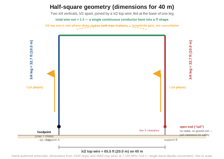
Step away from the single-radiator product families entirely, and the half-square answers a different question: what if, instead of engineering around the need for a ground return, you simply build the return path out of wire? A half-square is two quarter-wave vertical elements, spaced a half-wavelength apart, joined at the top by a half-wave horizontal wire and fed at the base of one of the two verticals — a single continuous run of wire roughly a full wavelength long, bent into a tall, narrow Π shape.
3.7.1 Why the currents add instead of cancel
Picture the two verticals as a simple in-phase array problem first. A pair of ordinary quarter-wave verticals, both fed identically from their own separate bases against a shared ground, radiate the same current in the same direction at the same time — but so does every point on the ground plane between them, and the pair does not automatically produce a directional broadside pattern just by proximity; that takes deliberate phasing hardware. The half-square gets its directionality a cheaper way, by using the geometry itself as the phasing network. The half-wavelength top wire is, electrically, a half-wave transmission-line/radiating section, and current flowing up the near (fed) vertical, across that half-wave top wire, and down the far vertical undergoes the natural 180° phase reversal a half-wavelength of wire imposes — so the current arriving at the top of the far vertical, and flowing down it, ends up in phase with the current flowing up the near vertical, when both are referenced to the same instant and the same “up is positive” convention. Two vertical currents flowing the same direction at the same time, spaced a half-wavelength apart, is exactly the condition for constructive addition broadside to the line joining them — the same physical mechanism, arrived at through the antenna’s own bent-wire geometry rather than a phasing harness, that a bobtail curtain or an in-phase vertical collinear array uses deliberately.
3.7.2 Feed and impedance
The antenna is fed in series at the base of one vertical leg — a genuine base feed at a current-maximum point, not an end-fed high-impedance connection, which is why the feedpoint impedance lands in a range directly compatible with ordinary coax rather than the thousands of ohms a true end-fed full-wave wire would present. Multiple independent sources converge on essentially the same figure: roughly 50–70 Ω, resistive near resonance, close enough to 50 Ω coax for a direct or near-direct match, occasionally trimmed with a small L-network or a slight off-resonance dimensional tweak to land exactly on 50 Ω. The far vertical’s bottom end is the true open end of the overall wire run — it terminates near ground but is not bonded to it, and needs no radial, ground rod, or counterpoise of its own; a modest ground stake at the fed corner is common practice for lightning/static drain and mechanical anchoring, not because the antenna’s electrical operation requires an earth reference there.
3.7.3 Why no radial field is needed
The reasoning traces directly back to Vol 1’s closing observation that even a quarter-wave monopole is “half of a dipole working against its own image,” and to Vol 2’s development of why a radial field exists at all — to supply, with a low-loss artificial conductor, the return-current path a base-fed vertical’s earth image would otherwise have to carry through lossy real soil. The half-square never creates that requirement in the first place: the “other half” of each vertical element’s effective circuit is not an earth image at all, it is the physically real half-wave top wire and the far vertical leg, both actual copper rather than a ground return. The whole Π-shaped structure is a closed, self-contained radiating loop — fed at a genuine base current-maximum exactly as Section 7.2 described, not at a high-impedance open end — that is critically independent of the earth beneath it for its current-return path. Field literature is consistent and blunt about the practical consequence: the half-square is described as self-contained, needing no ground screen or radial field, and — the detail that most surprises builders coming from vertical-array practice — a nearby ground plane or counterpoise can reduce rather than improve its performance, because the antenna’s design already assumes the return path is the wire, not the earth, and an unintended parasitic ground interaction competes with that assumption rather than helping it.
3.8 Half-square pattern and gain
3.8.1 Pattern shape
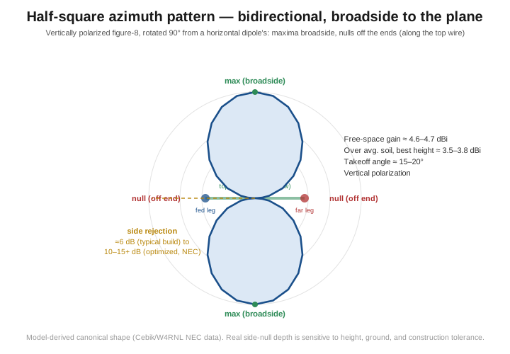
The half-square’s radiation pattern is the vertically polarized cousin of a horizontal dipole’s classic figure-8 — a genuinely unusual combination, since vertical polarization normally travels with the omnidirectional pattern Vol 1 derived for a plain monopole. Here, the two in-phase vertical currents produce a bidirectional pattern, broadside to the plane containing the two verticals and the top wire, with nulls off the ends — directly along the line the top wire runs. Practical modeling and field measurement both describe the side rejection (the nulls off the ends, in the antenna’s own plane) as substantial: NEC models of a well-optimized design commonly show 10–15 dB or more of side rejection, while more modest or non-optimized builds, and the figure most often quoted in casual ham literature, land closer to ~6 dB — the honest summary is that the null depth is real and useful for rejecting an unwanted direction or a local noise source, but it is sensitive enough to dimensional and height details that a specific number should be taken as representative rather than guaranteed for any particular installation.
3.8.2 Gain
NEC modeling by L. B. Cebik (W4RNL), the most rigorously documented source on this antenna’s performance, puts a well-optimized half-square’s free-space gain at roughly 4.6–4.7 dBi (using a horizontal-to-vertical leg ratio closer to 1.6:1 than the textbook exact λ/2-over-λ/4 proportions, traded for a few extra tenths of a dB), falling to roughly 3.5–3.8 dBi over average soil at the antenna’s best working height, with a takeoff angle in the 15–20° range — squarely in the low-angle DX window Vol 2 established as the vertical family’s whole reason for existing. Compared directly against a single quarter-wave vertical, published comparisons converge on a gain advantage of roughly 2.5–5 dB broadside, with the spread reflecting differences in comparison baseline (a bare vertical dipole versus a grounded quarter-wave monopole), height, and soil quality rather than genuine disagreement about the underlying physics. Whatever the exact number for a given installation, the half-square is unambiguously several dB ahead of a single vertical in its favored directions, at the cost of the 360° coverage a plain vertical offers and none of a half-square’s directional gain.
3.8.3 Comparison to alternatives
The half-square’s real market position is against a rotatable Yagi, not against another vertical: for roughly the material cost of two supports and some wire, an installer gets several dB of gain and useful front-to-side rejection in two fixed, opposite directions, without a tower, a rotator, or the expense either implies. It gives up the ability to swing the pattern anywhere on the compass the way a beam can — the half-square points wherever its plane is oriented, permanently, and reorienting it means physically relocating the supports. For an operator with two conveniently spaced trees or masts and a favored pair of opposite DX directions (say, transatlantic and transpacific paths that happen to fall roughly along the same line), that tradeoff is an excellent one; for an operator who needs to work every direction on the compass with beam-like gain, it is not the right tool, and a rotatable Yagi or a phased/switchable array of half-squares (a documented extension of this same geometry, though outside this volume’s scope) is the answer instead.
3.9 Half-square construction and deployment
3.9.1 Dimensions
The half-square’s two vertical legs are each the same quarter-wave length Vol 1’s length table already established for a plain vertical (234/f_MHz, in feet), and the horizontal top wire is a half-wave length by the same trim convention single-band dipoles use (468/f_MHz, in feet) — the two formulas are already internally consistent across the hub, and no new trim factor needs deriving:
Table 5 — The half-square's two vertical legs are each the same quarter-wave length [Vol 1](/fixed-vertical-monopoles/vol-1/)'s length table already established for a plain vertical (234/fMHz, in feet), and the horizontal top wire is a half-wave length by the same trim convention single-band dipoles use (468/fMHz, in feet) — the two formulas are already internally consistent across the hub, and no new trim factor needs deriving
| Band | Design freq | Vertical leg (λ/4, 234/f) | Top wire (λ/2, 468/f) | Support height needed |
|---|---|---|---|---|
| 80 m | 3.650 MHz | 64.1 ft (19.5 m) | 128.2 ft (39.1 m) | ~70 ft + safety clearance |
| 40 m | 7.150 MHz | 32.7 ft (10.0 m) | 65.5 ft (20.0 m) | ~35–40 ft |
| 20 m | 14.175 MHz | 16.5 ft (5.0 m) | 33.0 ft (10.1 m) | ~20–25 ft |
The vertical leg length is a hard geometric requirement, not a free design variable — the two supports have to be tall enough to hoist the top wire that high regardless of what height would otherwise be “optimal” for a vertical antenna. What is a free variable, and where the half-square breaks with ordinary vertical-antenna intuition, is how close to the ground the bottom “tails” (the open/fed ends of the two verticals) should sit.
3.9.2 Why lower tails work better, not worse
Vol 2’s takeoff-angle-versus-height development for a plain vertical carries an implicit assumption that more height (more radial-field clearance, less near-field ground interaction) generally helps. The half-square inverts that intuition for its own bottom ends specifically: because the antenna’s low-angle performance comes from the fixed leg-length geometry and the in-phase current condition Section 7.1 derived, not from clearing the tails further off the ground, raising the whole structure so the tails sit much higher than necessary degrades the pattern — it starts to develop off-the-end lobes it should not have and pushes more radiation upward at the expense of the low-angle lobe DX work wants. The practical guidance from builders is to keep the tails low — close to ground level, with just enough clearance (typically a few feet) to keep people and animals away from what is, electrically, a high-voltage open end — rather than treating “get it up in the air” as an unqualified good the way it is for Vol 2’s takeoff-angle curve on a plain vertical.
3.9.3 Practical build
A 40 m half-square needs two supports around 35–40 ft tall (trees, push-up fiberglass masts, or an existing tower used purely as a mechanical anchor) spaced roughly 65 ft apart, with #14 or #12 copper wire run up one support, across to the other, and back down, broken only at the base of the fed leg for the coax connection. A choke balun or common-mode current choke at the feedpoint is standard practice, exactly as it is for any wire antenna in this hub, to keep the coax shield from becoming an unintended part of the radiating structure. On a moderate residential lot with two trees roughly 60–70 ft apart, a 40 m half-square is a wire-and-rope build well under $100 in materials that meaningfully outperforms most commercial trap verticals broadside to its plane — the tradeoff, as Section 8.3 laid out, being the fixed bidirectional pattern in exchange for that gain.
3.10 Where this volume hands off
This volume took the generic quarter-wave monopole of Vol 1–Vol 2 and covered the two ways real installations go past a single bare vertical: buying a multiband commercial product, and building a directional wire array instead of a single omnidirectional radiator. On the commercial side, three genuinely different design philosophies share the “multiband HF vertical” shelf — the Hustler 4-BTV/5-BTV/6-BTV’s straightforward trap-and-radial-field approach (cheapest, narrowest per-band bandwidth, a real radial field is mandatory); the Cushcraft R-9/R-8’s end-fed half-wave topology, which genuinely eliminates the need for any earth-referenced ground system at the cost of a premium price and, currently, a supply gap following MFJ’s 2024 production halt; and the GAP Titan DX’s trap-free, elevated-feed, small-built-in-counterpoise design, which delivers the highest per-band efficiency of the three at the cost of a more wind-exposed mechanical structure. On the wire-array side, the half-square builds its own return current path out of a half-wavelength of real copper rather than relying on an earth image at all, trading the vertical family’s omnidirectional coverage for several dB of gain and useful front-to-side rejection broadside to its plane, at a price and complexity well below a rotatable Yagi.
Vol 4 picks up the remaining full-size-vertical problem this volume set aside: what to do when a full λ/4 (or the half-square’s even larger footprint) simply does not fit the available space, and the answer becomes electrical shortening — coil and capacitive-hat loading, the Chu-Harrington efficiency-versus-bandwidth limit those methods run into, and the Marconi-T-style loaded verticals that are the standard low-band answer for a residential lot. Vol 5 closes the dive with the hands-on side: a DIY build, the full commercial-buy survey across price tiers, companion gear, and the common gotchas and myths this volume’s “no radials” discussion already began correcting.
3.11 Resources
- ARRL Antenna Book (25th+ ed.), the multiband and phased-vertical chapters — the canonical reference for trap-vertical design and the half-square/bobtail-curtain family of in-phase vertical arrays.
- DX Engineering installation and product documentation for the Hustler 4-BTV/5-BTV/6-BTV, the 12 m and 17 m WARC add-on kits (DXE-AOKC-12M, DXE-AOKB-17M), and the 80 m add-on kit for the 4-BTV — the source for the verified band lineups, radial guidance, and current pricing in Section 3.
- Cushcraft R-7/R-8/R-9 assembly and installation manuals — the source for the explicit “do not connect to a ground radial system” guidance and the EFHW-derived design principle in Section 4.
- GAP Antenna Products technical literature (Titan DX) — the manufacturer’s own account of the elevated-feed, trap-free, small-counterpoise design principle in Section 5.
- Amateur Radio Newsline, coverage of the 2024 MFJ production halt and the 2026 Hy-Gain/Cushcraft brand acquisition by ITU Corporation — the source for the availability note in Section 4.2.
- L. B. Cebik (W4RNL), “Space-Conserving Verticals” antenna-modeling papers — the deepest NEC-derived treatment of the half-square’s gain, takeoff angle, and height sensitivity, archived across the antenna-modeling community and the primary source for Section 8’s figures.
- W8JI (Tom Rauch) technical notes on end-fed and ground-independent vertical antennas — a widely cited independent-engineering perspective on the real-world tradeoffs behind “no radials” marketing claims across this product category.
Comments (0)