Fixed Vertical Monopoles · Volume 4
Shortened & Loaded Verticals, and Choosing a Vertical
Base, center, and top/cap-hat loading and the current-distribution reason their efficiency ranks in that order; the radiation-resistance-falls-with-height-squared penalty, quantified; a genuine decision guide across full-size, trap, shortened-loaded, and half-square verticals; and the power-handling realities of insulators, loading coils, and the radial return path
4.1 About this volume
Vol 1 fixed the image-plane theory of the full-size quarter-wave monopole and its 36 Ω feedpoint. Vol 2 developed the low-angle radiation-pattern advantage and made the radial field’s efficiency tradeoff quantitative — the difference between a DX performer and a high-angle noise bucket. Vol 3 surveyed the full-size HF trap verticals that dominate the mid-priced commercial market and the half-square, a full-size two-element array that trades a second support point for roughly 2.5–5 dB of gain over a single vertical and a favored direction. Every one of those volumes assumed the builder has, or can find, the room for a genuine quarter-wave conductor.
Most builders don’t. A quarter-wave vertical on 80 m is 19–20 m of conductor; on 160 m it is close to 37–40 m — routinely taller than the mast, tower, or tree available on a residential lot. This volume covers the answer: shortening the physical radiator and adding reactance somewhere along it to restore electrical resonance, and the efficiency price that shortening always extracts. The price is not fixed — it depends heavily on where the compensating reactance goes, and the physics of why position matters is the technical heart of this volume. The second half turns from “how much does shortening cost” to the practical question every builder eventually faces: which of the four vertical families — full-size ground-plane, trap multiband, shortened-loaded, or half-square — actually fits a given lot, band plan, and operating goal, and when a vertical of any kind is the wrong antenna to reach for at all. The volume closes with the power-handling realities that are specific to loaded and full-size verticals alike: where the voltage lives, where the coil heats, and why the radial bond at the base carries every watt the antenna will ever put on the air.
4.2 Shortened and loaded verticals — the loading-position efficiency ranking
4.2.1 Why shortening forces a loading decision
A quarter-wave monopole is resonant because its open-circuit top and its driven base satisfy the same boundary condition Vol 1 built the standing-wave picture from: zero current at the free end, a quarter-cycle of current build-up down to the feedpoint. Cut the physical conductor shorter than a quarter-wave and that boundary condition can no longer be met by a simple sinusoid alone — the truncated element presents capacitive reactance at the feedpoint instead of the clean resistive match a full-size quarter-wave gives. Something has to cancel that capacitive reactance before the antenna is a sane load for a transmitter, and the only way to cancel reactance without adding physical length is to insert an equal and opposite inductive reactance in series with the radiator: a loading coil, or (functionally equivalent from the feedpoint’s point of view but implemented very differently) a capacitive top hat that changes the current and voltage distribution enough to bring the shortened structure back to resonance without inserting a discrete inductor at all.
The critical fact — and the one that separates a merely-shorter-than-ideal vertical from a genuinely compromised one — is that where the compensating reactance goes changes the current distribution on the whole element, and it is the current distribution, not the total electrical length, that sets how much of the antenna actually radiates.
4.2.2 The current-distribution argument: why position determines efficiency
A full-size quarter-wave vertical’s current is maximum at the base and tapers smoothly to zero at the tip — the same cosine-family taper Vol 1 derived from the standing-wave boundary conditions. Every increment of that current, all the way up the element, contributes to the far field. Shorten the conductor and load it, and the loading position decides how much of that current profile survives on the physical wire that’s left.
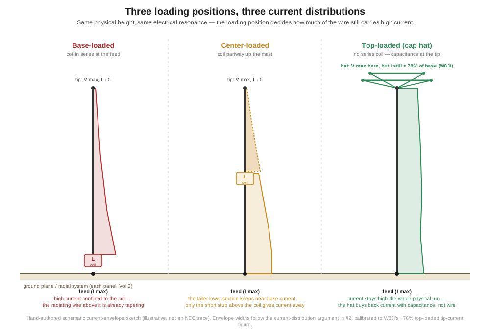
Base-loaded (the coil sits in series right at the feedpoint, between the transmitter and the conductor): the coil is now the point of highest current in the whole system, and the physical vertical section above it — however tall it happens to be — inherits a current distribution that tapers away from that already-reduced value toward zero at the tip, essentially a triangular taper compressed into a shorter physical run. The consequence, stated plainly by W8JI’s own analysis of loaded verticals, is that “the high current portion of the vertical exists in the coil rather than the driven element” — the current is doing its most vigorous work inside a component that does not radiate at all, and the wire that does radiate carries a current profile that has already started falling before it even gets going. This is the worst-performing loading position of the three, and it is also the mechanically simplest to build, which is exactly why it is the most common mistake in home-built shortened verticals.
Center-loaded (the coil sits partway up the physical structure, at or above its geometric midpoint): moving the coil upward shifts the high-current region down onto the physical vertical section below the coil, which now carries close to full current over its own length rather than the coil carrying it. The short vertical stub above the coil, out to the tip, still tapers away to zero current, but because that stub is short, the loss of radiating current there costs less than it would if the same taper were spread over the antenna’s entire physical height. Center loading is, in effect, a compromise that recovers most of the base section as a genuine high-current radiator while accepting a smaller, harder-to-avoid loss above the coil.
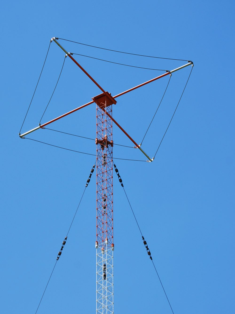
Top-loaded (capacitive hat): instead of an inductor anywhere on the wire, a horizontal capacitive structure — a spoked wire “hat,” a wire-cage umbrella, or (at broadcast scale) the wire disk photographed above — is added at the physical top. The hat’s shunt capacitance to the surrounding space does the job a series inductor would do elsewhere, but it does it at the open end rather than partway down, and the electrical effect on the current distribution is the opposite of base loading: instead of the current falling away toward the tip, the hat’s capacitance sustains a substantial current all the way to the physical top. In a concrete worked example from W8JI’s own analysis of an electrically very short (about 10° tall) 160 m radiator, a capacitive hat held the current at the physical top to roughly 78% of the base current — a far cry from the near-zero tip current an unloaded or base-loaded structure of the same height would show. The entire physical run of wire ends up carrying a current close to the base value, which is precisely the same “flat, high current over the whole physical structure” profile a longer radiator would have — the hat is buying back radiating current with capacitance instead of with wire.
The ranking that follows from this argument — top/cap-hat loading best, center loading next, base loading worst — is not a rule of thumb picked out of the amateur folklore; it is a direct consequence of where each technique places the current node relative to the physical, radiating conductor, and it is corroborated across the loaded-vertical literature: the ARRL Antenna Book’s treatment of shortened verticals recommends a capacitance hat “as large as practical” specifically to raise radiation resistance, and independent write-ups of loading-coil physics converge on the same ordering — “the higher the loading coil, the greater the efficiency,” with base-loading (or an antenna tuner doing the same job electrically at the feedpoint) explicitly called out as the worst commonly-used option.
4.2.3 Quantifying the penalty: radiation resistance falls with height squared
The current-distribution argument has a clean quantitative expression. For a short monopole, radiation resistance follows the standard small-antenna relation
R_r ≈ 160π² · (h_eff / λ)² Ω,
where h_eff is not the physical height of the radiator but its effective height — the current-weighted integral of the distribution over the physical length, normalized to the base current. h_eff equals the full physical height only in the limiting case of a perfectly uniform current from base to tip, which is exactly the condition a large, well-built capacitive hat is chasing; for the unloaded or base-loaded triangular taper, h_eff runs well under the physical height, because most of the wire is carrying only a fraction of the base current. Squaring a fraction makes the penalty worse than it looks at first glance: an antenna whose current taper leaves it at, say, half its geometric height in effective-height terms does not lose half its radiation resistance — it loses three-quarters of it, because the relation is quadratic.
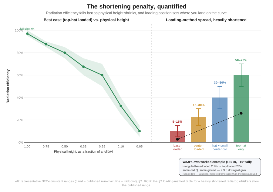
This is the mechanism behind W8JI’s worked numerical example for the electrically very short (~10°-tall) 160 m case cited above. At 100 W input into a Q = 200 loading coil over an idealized perfect ground, the triangular (unloaded/base-loaded) current distribution gave a radiation resistance of roughly 0.3 Ω, radiating about 2.7 W — a 2.7% radiation efficiency, with the remaining 97.3% of the input power dissipated as heat in the coil and system losses. Adding a capacitive top hat, and thereby holding the current near its base value all the way to the physical top, raised the radiation resistance to roughly 0.97 Ω — about 3× higher — which raised the radiated power to 26 W, a 26% efficiency, and a 9.8 dB improvement in radiated signal for the identical antenna height and the identical coil. That nearly-10 dB swing, for the same physical footprint, is the entire case for reaching for top loading over base loading whenever the mechanical design allows it.
The same worked example carries an important second lesson. Repeating the top-loaded case over a realistic lossy ground (20 Ω of ground-loss resistance added in series, in place of the idealized perfect-ground assumption) dropped the radiated power to about 4.1 W — a 4.1% efficiency, still roughly 6.3 dB better than the base-loaded case at the same ground quality, but about 8 dB worse than the perfect-ground top-loaded result. In other words, the benefit of good loading position shrinks once a larger loss — here, ground loss — dominates the total loss budget; the same source notes that doubling coil Q from 200 to 400 is worth close to 2.8 dB improvement over an idealized perfect ground, but only about 0.8 dB once 20 Ω of ground loss is stacked in series, because the ground loss “dilutes” or “swamps out” the benefit of any one component’s improvement. This is exactly the Vol 2 radial-field argument recurring in a different guise: fixing whichever loss dominates the system — ground loss, coil loss, or an inefficient current distribution — pays off first, and improving a component that isn’t the bottleneck buys very little.
A representative, order-of-magnitude picture of how these effects compound as an antenna is progressively shortened, drawn from the same body of shortened-vertical literature and consistent with the Vol 2 ground-loss framing, looks like this:
Table 1 — A representative, order-of-magnitude picture of how these effects compound as an antenna is progressively shortened, drawn from the same body of shortened-vertical literature and consistent with the [Vol 2](/fixed-vertical-monopoles/vol-2/) ground-loss framing, looks like this
| Physical height (fraction of a full λ/4) | Best achievable efficiency (top-hat loaded) | Typical 2:1 SWR bandwidth |
|---|---|---|
| 1.00 (full λ/4) | 95%+ | 5–8% |
| 0.75 | 85–90% | 4–6% |
| 0.50 | 75–85% | 3–5% |
| 0.33 | 60–75% | 2–4% |
| 0.25 | 50–70% | 1.5–3% |
| 0.10 | 25–40% | 0.5–1% |
| 0.05 | 5–15% | <0.5% |
And, at the shortest end of that table — a heavily shortened vertical at a small fraction of a full λ/4, a genuinely common size for a low-band restricted-space installation — the same loading-position ranking reappears as an efficiency spread rather than a single number:
Table 2 — And, at the shortest end of that table — a heavily shortened vertical at a small fraction of a full λ/4, a genuinely common size for a low-band restricted-space installation — the same loading-position ranking reappears as an efficiency spread rather than a single number
| Loading method (heavily shortened, well under λ/4) | Representative efficiency | Notes |
|---|---|---|
| Top-hat only, no coil | 50–70% | Best; the Marconi T and broadcast “umbrella” antennas |
| Top-hat + a small center coil | 30–50% | The common hybrid — most compact commercial verticals |
| Center-loaded, no hat | 15–30% | Mid-range; the ARRL’s “coil about halfway up” compromise |
| Bottom (base)-loaded | 5–15% | Worst of the four; also the simplest to build |
Both tables are representative NEC-consistent ranges rather than a single closed-form prediction for any specific installation — the exact number for a given build depends on conductor diameter, coil Q, hat size, and ground quality exactly as Vol 2’s radial-efficiency tables depend on soil and radial count — but the direction and rough magnitude of every entry is well established, and the ARRL Antenna Book’s own general guidance — that inductively loaded verticals should generally not be shortened past about 50% of full size before the efficiency and bandwidth penalties become severe — is the same conclusion stated as a rule of thumb rather than a curve.
The bandwidth column in the first table is not a second, unrelated penalty riding along with the efficiency column — the two are coupled by the same underlying physics. The Chu-Harrington limit on electrically small antennas states that a radiator’s achievable bandwidth and its achievable efficiency both shrink together as the structure is packed into a smaller fraction of a wavelength, and the product of the two is bounded by the antenna’s enclosing volume: there is no clever feed network or exotic loading geometry that lets a genuinely small antenna have both wide bandwidth and high efficiency at once, because the limit is a statement about stored reactive energy relative to the sphere the antenna occupies, not about any particular implementation. A heavily shortened vertical’s shrinking 2:1-SWR bandwidth in the table above and its falling radiation efficiency are therefore the same Chu-Harrington constraint showing up on two different meters — a loading scheme that appears to buy back bandwidth without paying an efficiency price, or vice versa, should be treated with the same skepticism as a claimed free lunch, because the limit does not have an escape clause for good engineering.
4.2.4 Capacitance hats: raising effective height without physical height
Mechanically, a capacitive hat is a small horizontal (or slightly domed) structure of wire spokes, a wire cage, or — as in the broadcast-scale photograph opening this volume — a wire-and-guy umbrella, mounted at the physical top of the shortened radiator and electrically bonded to it. Two to eight radial wires 1–3 m long is a typical amateur-scale hat; the wires need not form a solid disk, because the capacitance the structure adds is bulk dielectric loading against the surrounding free space, not a low-loss conductor area the way a ground-plane radial is. The rule that follows directly from the radiation-resistance relation above is that a larger hat is a better hat: more capacitance holds the current closer to its base value further out along the physical wire, pushing h_eff closer to the true physical height and the radiation resistance closer to the full-size figure. The ARRL Antenna Book’s advice to build the hat “as large as practical” is this same physics stated as a design instruction rather than a formula.
The classic amateur embodiment of top loading, the Marconi T, takes the idea to its logical mechanical conclusion: rather than a compact hat at the very top, a substantial run of horizontal wire — commonly on the order of 1.5 quarter-wavelengths — feeds into the top of a much shorter vertical section (typically a quarter to half of a full λ/4), with the horizontal run itself acting as a large-area top-loading capacitor while also serving as the mechanical span between two supports. The result is a shortened low-band vertical with genuinely respectable efficiency by the standards of the loading-position ranking above, and it remains the standard restricted-lot 160/80 m home-station antenna for exactly that reason: it buys most of the top-loading benefit using wire the builder likely has to string anyway between two supports.
4.2.5 Screwdriver and continuously-variable loading-coil verticals
Mobile HF operation adds a further wrinkle: the physical whip is fixed by what fits on a vehicle, but the operating band changes constantly, so the loading reactance has to be adjustable rather than cut once for a single design frequency. The “screwdriver” antenna — named for the small DC gearmotor (historically resembling an electric screwdriver’s motor) that drives it — places a continuously variable-inductance coil partway up a fixed-length whip and lets the operator retune the effective loading, and therefore the resonant band, from inside the vehicle without touching the antenna. Electrically this is a center-loading design whose coil position is fixed by the mechanical assembly but whose inductance (and, in most designs, roughly its electrical “position” within the total series reactance) is adjustable in real time — it sits squarely in the center-loaded middle tier of the ranking above rather than at either extreme, trading some of top-loading’s efficiency ceiling for band-agility a fixed hat cannot offer.
A related, larger-coil cousin — the “bugcatcher” style loading coil, after the Texas Bug Catcher and its descendants — uses a substantially larger-diameter, larger-turn-count coil, usually with a mechanical or manual tap rather than a motor-driven continuous adjustment, mounted at a fixed point on the mast. Because the coil itself is physically larger, it generally carries a higher Q than the compact coil packed into a motor-driven screwdriver mechanism, and — for the same loading position on the whip — a well-built bugcatcher coil is commonly reported to outperform a compact screwdriver coil, at the practical cost of losing the screwdriver’s from-the-driver’s-seat retuning convenience. Neither design escapes the fundamental height-versus-efficiency tradeoff of this section; a 6 ft mobile whip loaded to resonate on 80 m is operating at an electrical height a small fraction of a full quarter-wave regardless of which loading hardware does the job, and single-digit-percent radiation efficiency is what the physics of that geometry allows no matter how well the coil is built. The deep mobile-antenna build-out — ham-sticks, MP-1/AX-1, and the rest of the portable/mobile family — is the companion Portable & Mobile Monopoles dive’s subject ↗; this volume’s job is only to place screwdriver and bugcatcher designs correctly on the loading-position efficiency ranking developed above.
4.3 Choosing a vertical — full-size, trap, shortened-loaded, or half-square
4.3.1 When a vertical is the right call
Vol 2 already made the core case: a competently grounded quarter-wave vertical puts its peak radiation at 20–30° elevation, exactly the angles transcontinental and intercontinental HF propagation arrives at, where a horizontal dipole at ordinary residential height has already rolled off. That low-angle, omnidirectional-in-azimuth pattern is the right tool whenever the operating goal is DX rather than regional contacts, whenever the lot has no horizontal real estate but does have vertical clearance (a small urban lot, a townhouse with a single accessible corner, a mast where a sprawling dipole or inverted-V simply will not fit), and whenever the goal is coverage in every azimuth direction without having to rotate or reorient anything — a genuinely useful property for casual ragchewing, for a station that works DX in more than one direction, or for any installation where a single fixed favored direction would be the wrong compromise. Restricted-azimuth-space situations — a lot with buildings or trees close on two sides but a clear vertical run available — are the vertical family’s signature niche, and within that niche the specific choice of full-size, trap, shortened, or half-square (worked through below) is what actually determines how well the installation performs.
4.3.2 When a vertical is the wrong call
The same properties that make a vertical the right tool for low-angle DX make it the wrong tool for two specific and common situations. High-angle NVIS work — 40 m and below, short-skip and regional nets — wants a low horizontal dipole, not a vertical, because NVIS needs strong radiation straight up, and a vertical’s pattern has its hard null exactly there: Vol 2’s toroidal donut has the hole pointing at the zenith by construction, which is precisely the one direction NVIS traffic needs illuminated. Reaching for a vertical for a regional 75 m net is choosing the antenna whose null points at the target.
Quiet receive and contest signal-to-noise is the second wrong-call case, and it deserves to be taken as seriously as the low-angle gain advantage that makes verticals attractive in the first place. Most local electrical noise — switching power supplies, LED-driver hash, power-line arcing — is predominantly vertically polarized, so a vertical antenna is preferentially coupled to exactly that noise in a way a horizontal antenna is not, and the same low-angle sensitivity that helps a vertical hear distant DX signals also opens it up to distant low-angle noise sources. The resulting receive-noise penalty, commonly cited in the low-band-DX and contest literature at somewhere in the 6–15 dB range relative to a horizontal dipole at the same site, is large enough that serious DX and contest operations routinely split the job: transmit on the vertical (or the half-square, or whatever low-angle gain antenna the station has), and receive on a dedicated low-noise antenna instead — a Beverage, a terminated loop, or another receive-only design from the companion Receive-Only Loops dive ↗. A single-antenna casual station does not need to build that second antenna, but it should go in with eyes open: a vertical that “sounds noisy” compared to the dipole it replaced is very likely working exactly as the physics predicts, not malfunctioning.
4.3.3 Full-size vs trap vs shortened-loaded vs half-square — a decision matrix
Given that a vertical of some kind is the right call, the next decision is which vertical family fits the site. The four options this dive covers pull against each other on four axes — the height budget available, how many bands need to be covered from one feedline, whether the goal is pure DX gain or general-purpose coverage, and whether a proper radial field (buried or elevated) is actually feasible to install — and laying them out side by side makes the tradeoffs explicit rather than buried in four separate volumes’ worth of prose.
Table 3 — Full-size vs trap vs shortened-loaded vs half-square — a decision matrix
| Constraint | Full-size λ/4 ground-plane (Vol 1–Vol 2) | Trap multiband vertical (Vol 3) | Shortened & loaded vertical (this volume, §2) | Half-square (Vol 3) |
|---|---|---|---|---|
| Height budget | Full λ/4 required (20 m on 80 m, 37+ m on 160 m) | Full λ/4 of the highest band covered, same as full-size | Deliberately compressed — the whole point is fitting a restricted mast/lot | Larger footprint than a single vertical: two support points, λ/2 apart, each ≥ λ/4 high |
| Bands from one feedline | Single-band only | Multiple bands (4–7 typically) on one feedpoint | Usually single-band per loaded structure (unless the loading is switched/retuned) | Single-band, same as full-size |
| Efficiency | Highest achievable — the reference case | Per-band trap loss (~0.5–0.6 dB/band, worse on the lowest band, per Vol 3) but otherwise near full-size on each covered band | The genuine efficiency penalty of §2 — from near-full-size down to single-digit percent at extreme shortening | Full-size-element efficiency, plus array gain |
| Gain / directivity | 5.15 dBi free-space reference; omnidirectional azimuth | Same reference gain per band, omnidirectional azimuth | Reduced gain proportional to the §2 efficiency penalty; still omnidirectional azimuth | Roughly 2.5–5 dB over a single vertical, favored direction, ~6–15 dB front/side rejection (Vol 3) |
| Radial-field feasibility | Wants a full buried or elevated radial field (Vol 2) | The Hustler BTV traps want a full radial field; the no-radial multiband verticals (Cushcraft R-9, GAP Titan DX) are a distinct topology (Vol 3), not traps, and need no radial field at all | Still wants radials in principle, but is often the choice precisely where radial space is also short | None required at the base — self-contained like a vertical dipole |
| Best-fit case | Single-band DX station with the room to do it right | ”One feedline, whole HF band-plan” convenience, moderate budget | Low-band (80/160 m) coverage on a restricted lot where a full-size vertical will not physically fit | A lot with two supports λ/2 apart and a specific favored DX direction, in place of a rotatable Yagi |
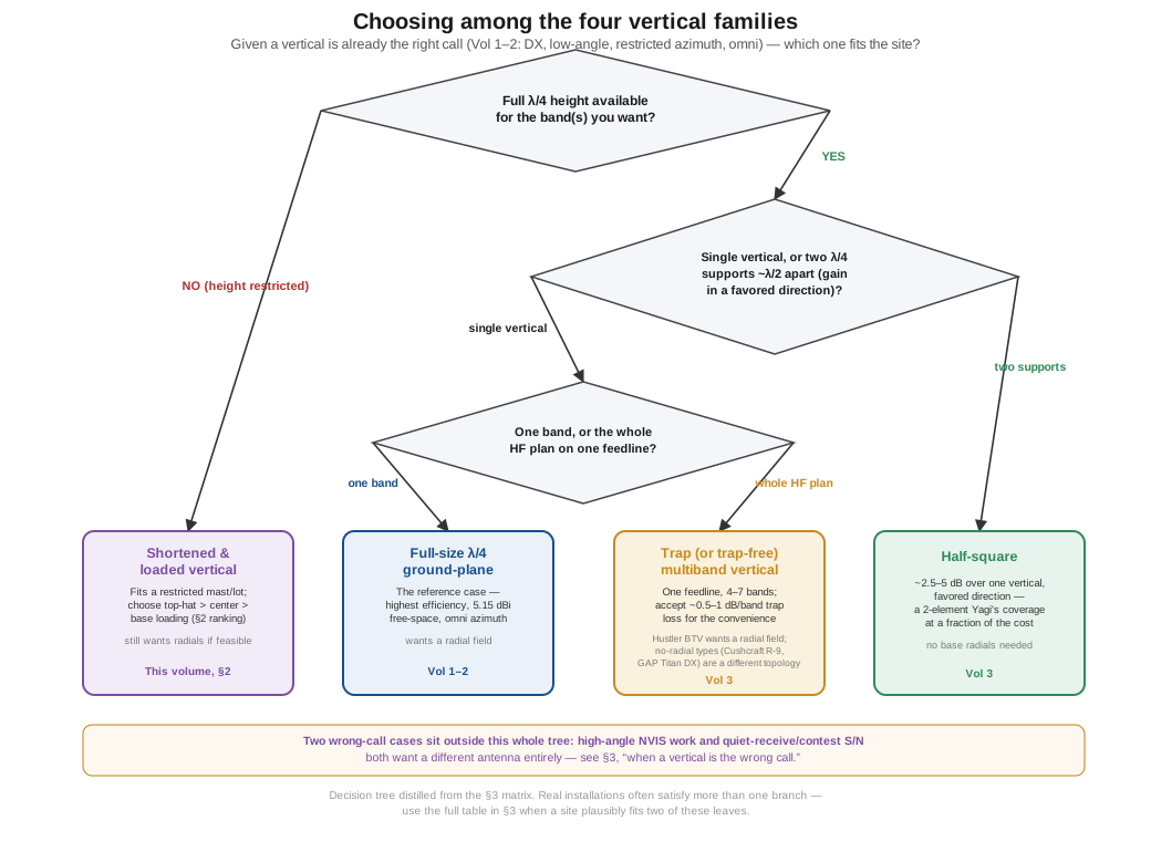
Reading the table by scenario rather than by column: a builder with the full height budget and the radial space should simply build (or buy) the full-size single-band vertical Vols 1–2 cover — it is the reference case every other row is measured against, and every compromise below costs something relative to it. A builder who wants the whole HF band plan behind one feedline and has the moderate height a trap or trap-free multiband design needs (roughly 6.6–7.6 m for the Hustler BTV and GAP Titan DX lines Vol 3 surveys; the Cushcraft R-9 runs taller, ~9.6 m) should reach for a trap (or trap-free) multiband vertical, accepting the modest per-band trap loss — or, for the trap-free GAP design, the ground-loss/matching-network tradeoff Vol 3 works out — as the price of not running four or five separate feedlines. A builder whose height budget genuinely cannot accommodate a full quarter-wave — the common case on 80 and especially 160 m from a residential lot — is choosing between accepting the shortened-loaded penalty this volume quantifies (and choosing top-hat over base loading whenever the mechanical design allows it) or not operating that band from that location at all; there is no third option that avoids the physics. And a builder with two supports a half-wavelength apart and a specific direction worth favoring — a known DX path, or a direction away from a local noise source — gets more out of the half-square’s array gain and front-to-back ratio than out of any of the other three, at the cost of a second support point Vol 3 already spelled out.
4.4 Power handling — insulators, loading-coil heat, and the radial return path
4.4.1 Voltage distribution and the base and tip insulators
A properly matched, directly-fed vertical — full-size or shortened-loaded, resonant at the operating frequency — sits at a current maximum and voltage minimum right at the base, the same standing-wave relationship Vol 1 established for the full-size case. That means the base insulator’s job, in the textbook resonant case, is mechanical rather than high-voltage dielectric duty: it isolates the radiator from a grounded mount so the radial system, not the mast, is the RF ground reference, and it needs to survive weather and mechanical load far more than it needs a serious voltage rating. That comfortable picture changes the moment the antenna is operated off its exact resonance — a multiband switched-loading design between band changes, a screwdriver antenna mid-retune, or any installation being driven through an antenna tuner rather than fed directly at a clean resonance — because SWR-driven reactive voltage swings back up toward the feedpoint under those conditions, and a base standoff that was designed only for the low-voltage resonant case can find itself under real stress. Shunt-fed and gamma-matched tower-as-radiator installations are a related special case worth flagging explicitly: the insulated standoff that isolates the matching network from the grounded tower structure genuinely does sit in a higher-voltage region than a simple base-fed vertical’s insulator, and deserves a voltage rating chosen for that duty rather than borrowed from a base-fed design.
The one location that is always at a voltage maximum, in every vertical this dive covers, is the physical open end — the tip of a full-size quarter-wave, or, for a shortened-loaded design, the tip of the physical conductor and, in particular, the capacitive hat itself, which by construction sits exactly at that peak-voltage point. Shortening the physical wire does not lower the peak voltage the antenna must sustain to deliver a given power — the same reactive voltage swing that a full-size quarter-wave spreads out over its whole physical length gets compressed into a shorter run on a loaded design, and at legal-limit power (1.5 kW PEP) that voltage runs into the same low-kilovolt territory the sibling Single-Band Dipoles dive documents at a half-wave dipole’s open ends. A cap hat’s spokes and their support insulators need real corona-safe clearance and a genuine voltage rating for that reason — solder-lugged hardware sized for a 12 V automotive accessory is not adequate at amplifier power, however tempting it is to reach for on a shortened mobile or portable build.
4.4.2 Loading-coil heating and flashover
A loading coil dissipates real power as I²R_coil, where R_coil is set by the wire gauge, winding geometry, and — critically — the coil’s Q. §2’s worked example already showed how much this matters in absolute terms: at a modest Q of 200 over an idealized perfect ground, a loading coil in a heavily shortened vertical was dissipating on the order of 97% of the input power as heat rather than radiating it, before any hat was added. That heat has to go somewhere, and it is precisely why base-loaded designs — which put the coil at the point of highest current in the whole system — are also the designs most prone to physically overheating the coil at sustained high duty cycle; several popular bottom-loaded portable and mobile verticals are documented in the mobile-HF literature as running hot enough on digital or contest-style duty cycles to soften or melt their coil forms at power levels well under an amplifier’s legal limit, which is a mechanical failure mode layered directly on top of the radiation-efficiency penalty §2 already described. Moving the coil up-mast (center loading) reduces this heating for the same reason it improves radiation efficiency: less of the total system current is forced through the coil in the first place.
A separate and distinct hazard is flashover — arcing across adjacent turns of the coil, or between the coil and a nearby grounded structure, when the reactive voltage swing across a high-inductance coil at HF exceeds the winding’s insulation or the surrounding air’s breakdown strength. This is a voltage-stress problem, not the same as the current-heating problem above, and it does not track the loading-position ranking the same way: a compact, high-inductance coil built for a low band can develop a large V = I·X_L across its own winding regardless of whether it sits at the base, the center, or is combined with a hat, and manufacturers of high-power loading coils address it with generous turn spacing, larger-diameter low-loss wire or tubing, and — at the top tier — vacuum or gas-dielectric construction rather than simple air-wound magnet wire. Full-size and shortened verticals alike need a coil, trap, or hat genuinely rated for the intended power, and the rating has to account for both the thermal (I²R) and the dielectric (I·X_L, flashover) failure modes separately, because a coil that survives one comfortably can still fail the other.
4.4.3 Trap power limits, revisited
Multiband trap verticals share the loading-coil’s heating concern in a related component: the series LC trap. Vol 3 already surveyed the commercial trap-vertical market and the per-band trap-loss penalty each design accepts; the power-handling consequence is that traps, like loading coils, dissipate real power at their operating band’s resonance and are the failure point that shows up first under sustained legal-limit operation — a trap driven past its rating typically fails open with an audible “ping,” after which the antenna’s SWR on that band goes to effectively infinite until the trap is repaired or replaced. Commercial trap verticals rated at 1.5 kW SSB are rated for that duty cycle specifically; running one at full legal-limit power on a high-duty-cycle mode (RTTY, FT8-adjacent digital modes held at 100% duty, or continuous carrier testing) shortens trap service life relative to the SSB rating the manufacturer actually tested against, exactly as it does for the loading coils in this volume’s shortened designs.
4.4.4 The radial system as a return-current conductor
Every watt the vertical transmits leaves the base as current, and at the base that current has to divide across every radial the system provides, sum back together at the common bonding point, and return to the transmitter’s ground reference with as little resistive loss as possible — Vol 2’s entire radial-efficiency argument is, in the end, a statement about how well that current-summing junction is built. At legal-limit power into a well-matched 36–50 Ω feedpoint, the base current runs several amperes RMS (roughly √(1500/45) ≈ 5.8 A for a representative 45 Ω match), and that full current is what every radial-to-common-point bond has to carry without adding meaningful series resistance of its own. A crimped, corroded, or single-point-of-failure radial bond is exactly the kind of localized I²R loss Vol 2 already flagged as ground loss’s more avoidable cousin — the radial wire may be doing its job perfectly, but a poor mechanical bond at the one point where every radial’s current converges undoes a meaningful fraction of the whole radial field’s benefit, and it does so silently, without necessarily moving the SWR reading enough to be noticed. A corrosion-resistant common bus, soldered or properly clamped rather than merely twisted, is cheap insurance relative to the radial field itself and belongs at the top of any fixed-vertical maintenance checklist, alongside the periodic inspection the companion grounding and lightning-protection material covers in full ↗.
4.5 Where this volume hands off
This volume took the fixed-vertical family from the full-size reference case Vols 1–3 established into the compromises a restricted height budget forces. Loading position is not a detail — it is the single variable that determines whether a shortened vertical is a mildly compromised DX antenna or a single-digit-percent-efficient heating element, because it determines how much of the physical, radiating conductor still carries current close to its base value: top/cap-hat loading preserves the most, base loading preserves the least, and center loading and hybrid top-hat-plus-coil designs sit between them, exactly as the current-distribution argument and the R_r ∝ h_eff² relation both predict and as W8JI’s own worked numbers (2.7% vs. 26% efficiency, a 9.8 dB swing, on the same physical antenna) demonstrate concretely. The choice of vertical family — full-size, trap multiband, shortened-loaded, or half-square — is a genuine decision with real tradeoffs on height, band count, gain, and radial feasibility, not a single “best” answer, and a vertical of any kind is the right tool specifically for low-angle DX and restricted-azimuth real estate, and the wrong tool for NVIS and for quiet receive. Power handling on a loaded vertical lives in the same three places it lives on a full-size one — the insulators, the loading hardware, and the radial bond — with the loading coil and cap hat adding their own thermal and dielectric failure modes on top of the trap and insulator concerns Vol 3 already raised.
Vol 5 closes out this dive with the hands-on side: a step-by-step DIY build (the 20 m elevated ground-plane this hub’s original migrated content sketched, carried forward and verified against current vendor parts), the ranked commercial-buy survey across all four vertical families this dive covers, the companion gear — radial wire, bonding hardware, mounts, feedline, lightning protection — every vertical in this dive depends on, and the gotchas and myths that recur across fixed-vertical installations generally.
4.6 Resources
- ARRL Antenna Book (25th+ ed.), Ch. 9 (vertical antennas) — the canonical treatment of shortened and loaded verticals, the capacitance-hat “as large as practical” guidance, and the general “don’t shorten past ~50%” rule of thumb used throughout this volume.
- W8JI (Tom Rauch), “Short Verticals” and “Mobile Antennas, Short Verticals, Loading Coil Loss, and Loading Coil Current” (w8ji.com) — the worked numerical example (triangular vs. top-loaded current distribution, 0.3 Ω vs. 0.97 Ω radiation resistance, 2.7% vs. 26% efficiency, 9.8 dB) this volume’s quantitative case rests on, and the ground-loss “dilution” argument in §2.
- K7MEM, “Short Loaded Vertical” and W0BNC, “Loading Coils” — independent corroborating treatments of the base/center/top current-distribution argument and the loading-position efficiency ranking.
- Balanis, Antenna Theory: Analysis and Design (4th ed.) — the short-dipole/monopole radiation-resistance derivation (
R_r ∝ (h_eff/λ)²) this volume’s §2 builds on. - ON4UN, Low-Band DXing (5th ed.) — the authoritative 80/160 m shortened-vertical and Marconi-T reference for serious low-band DXers.
- Stutzman & Thiele, Antenna Theory and Design (3rd ed.) — complementary treatment of loaded and electrically-small antenna behavior.
Comments (0)