Receive-Only Loops & Specialty Receive Antennas · Volume 1
Why a Receive Antenna Is a Different Machine
The noise regime rebuilt in one honest unit, the insight the previous edition gets exactly right, and the figure of merit it uses throughout — which runs to infinity while the thing it stands in for is capped a shade above six decibels
1.1 About this volume
Every other antenna in this hub was designed to transmit. Efficiency was the point, loss was the enemy, and a figure quoted in decibels below isotropic was a confession. This dive covers the antennas where all of that is inverted — where thirty decibels of loss is a design feature and the only quantity that matters is the ratio of what you want to what you do not.
The previous edition opens with that inversion and states it well. Its §2.2 is the best paragraph in the chapter: loss attenuates the wanted signal and the noise arriving with it equally, so it cancels out of the signal-to-noise ratio, and what you buy with it is direction. That is exactly right, it is the reason this family of antennas exists, and nothing in this volume disturbs it.
What this volume does disturb is the number the chapter uses to measure the benefit.
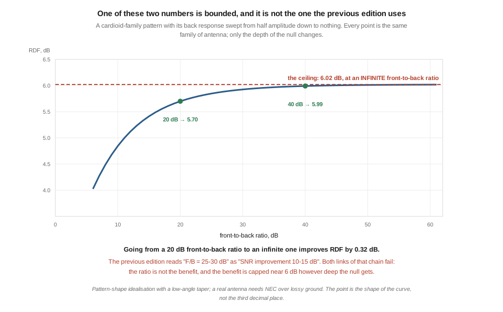
The chapter’s figure of merit is front-to-back ratio, quoted in the performance table of every antenna and converted directly into an “SNR improvement vs dipole”. §4 shows this cannot work, and the demonstration is three lines of arithmetic: an ideal cardioid has an infinite front-to-back ratio. Its null is perfect; nothing arrives from behind it at all. If front-to-back ratio were the SNR benefit, that antenna would improve reception without limit. Its actual benefit against noise spread over the sky is about six decibels.
So the two quantities are not two views of one thing. One is bounded and the other is not, and the chapter’s tables are built on the unbounded one.
The noise table the whole argument rests on also needs rebuilding. §2.1 puts two columns of field strength and one column of power into the same table and then subtracts them, which cannot be done without an antenna factor the chapter never supplies. §2 rebuilds it from ITU-R P.372 in one consistent unit. ⚠ The chapter’s conclusion survives the rebuild intact — external noise really does dominate a receiver through the whole of HF — but the magnitudes were overstated by around forty decibels.
And in rebuilding it, §5 finds a crossover the chapter never mentions, which answers the question §4 raises: at a quiet site, across essentially the whole of HF, the noise floor is set by the galaxy rather than by human activity. Galactic noise arrives from the entire sky. That is the case in which the chapter’s figure of merit does the least good, and it is the case a low-band operator spends most of the night in.
1.2 What the receiver is actually listening to
The chapter’s argument begins with a claim that is correct and important: below about 14 MHz a receiver’s own noise figure is irrelevant, because external noise sits far above it. Everything else follows. If the receiver is not the limit, then sensitivity is not what you are buying when you put up a receiving antenna, and directivity is.
The table offered in support does not support it.
§2.1 lists “Atmospheric noise (dBμV/m/Hz)” and “Man-made noise (urban)” alongside “Typical receiver NF”, giving −5, −5 and −130 at 1.8 MHz, then draws its conclusion by subtraction: “atmospheric noise + man-made noise is 100+ dB above the receiver’s internal noise.”
🔴 The first two columns are field strengths and the third is a power level. Converting between them needs the antenna factor of a specific antenna, which is the very thing under discussion and is never given. As written the subtraction does not compare like with like, and the numbers correspond to no standard noise convention.
1.2.1 Rebuilt from the source
The standard treatment is ITU-R Recommendation P.372, which expresses every noise contribution as Fa, an external noise figure in decibels above kT₀ — a single unit in which a receiver’s own noise figure sits on the same axis with no conversion at all. For man-made noise the Recommendation gives
Fa = c − d · log₁₀(f), with f in MHz,
and Table 1 supplies the constants:
Table 1 — and Table 1 supplies the constants
| Environmental category | c | d |
|---|---|---|
| City (curve A) | 76.8 | 27.7 |
| Residential (curve B) | 72.5 | 27.7 |
| Rural (curve C) | 67.2 | 27.7 |
| Quiet rural (curve D) | 53.6 | 28.6 |
| Galactic noise (curve E) | 52.0 | 23.0 |
“Note that equation (13) is valid in the range 0.3 to 250 MHz for all the environmental categories except those of curves D and E as indicated on the figure.”
⭐ These were read out of the Recommendation itself rather than from a secondary summary. That matters here: the constants are widely reproduced and widely mangled, and this dive has an established preference for the publication over the digest.
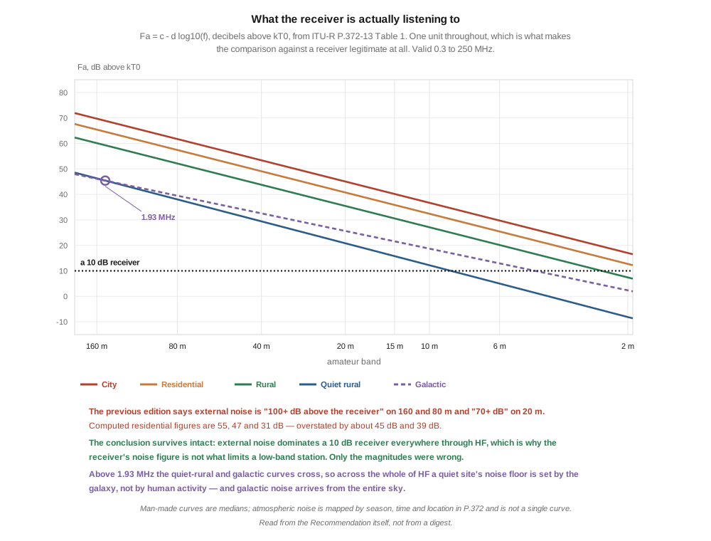
Evaluated across the amateur bands against a receiver with a 10 dB noise figure — the figure the chapter itself assumes:
Table 2 — Evaluated across the amateur bands against a receiver with a 10 dB noise figure — the figure the chapter itself assumes
| band | city | residential | rural | quiet rural | galactic | residential − receiver |
|---|---|---|---|---|---|---|
| 160 m | 69.7 | 65.4 | 60.1 | 46.3 | 46.1 | 55.4 |
| 80 m | 61.7 | 57.4 | 52.1 | 38.0 | 39.5 | 47.4 |
| 40 m | 53.4 | 49.1 | 43.8 | 29.4 | 32.6 | 39.1 |
| 20 m | 45.1 | 40.8 | 35.5 | 20.8 | 25.6 | 30.8 |
| 15 m | 40.2 | 35.9 | 30.6 | 15.8 | 21.6 | 25.9 |
| 10 m | 36.7 | 32.4 | 27.1 | 12.2 | 18.7 | 22.4 |
| 2 m | 17.0 | 12.7 | 7.4 | −8.1 | 2.4 | 2.7 |
🔴 The chapter says “100+ dB above the receiver” on 160 and 80 metres; the figure is 55 dB. It says “70+ dB” on 20 metres; the figure is 31 dB. Overstated by about forty-five and thirty-nine decibels respectively.
⚠⚠ And the conclusion is untouched. Fifty-five decibels of margin is not a diminished version of the chapter’s claim — it is the same claim. A receiver contributing 10 dB against an external floor of 65 dB degrades the system by an amount nobody can hear. The correct response is to fix the magnitudes and keep the finding, not to soften it into a hedge. There is no HF band on which a modern receiver’s noise figure is what limits a low-band station.
⭐ This hub’s own card for the dive already had it right, incidentally, describing external noise as dominating “by 20+ dB” — which brackets the computed range of 22 to 55 dB correctly. The chapter and the card disagreed, and the card was the reliable one.
⚠ One thing the table cannot do. Atmospheric noise is not a formula. P.372 supplies it as a family of maps varying with frequency, season, time of day and geography, and the Recommendation warns explicitly that some of its lower plotted values “should be used with caution, as they represent only estimates of what atmospheric noise levels would be recorded if the other types of noise were not present.” The man-made curves above are medians of measurements made in the 1970s, which the Recommendation itself notes “may change with time.” Treat the table as the right shape and the right order of magnitude, which is all the argument needs.
1.3 The insight the previous edition gets right
Having established that the receiver is not the limit, the chapter draws the correct and slightly startling conclusion. This section exists to endorse it rather than to correct it.
If external noise sets the floor, then making the antenna less efficient costs nothing, so long as the signal stays above the receiver’s own noise. Attenuate everything by 30 dB and the wanted signal falls 30 dB, the noise arriving from the same direction falls 30 dB, and the ratio between them — the only thing the operator can hear — is unchanged. What you have bought is the freedom to design for pattern instead of for efficiency, and pattern is the one thing that can change the ratio.
⭐ That trade is genuinely unavailable to a transmitting antenna, and the chapter is right to say so. A transmitter’s loss is power that never leaves the property. This is the sharpest available statement of why the two families look so different, and why an antenna that would be an embarrassment on transmit — thirty decibels below a dipole, a fraction of a percent efficient — can be the best thing on the property for listening.
⭐ It also explains a feature that otherwise looks perverse: the antennas in this dive are frequently terminated in a resistor, deliberately throwing energy away. §2.3 has that right too. The resistor absorbs the wave that would otherwise reflect from the far end and travel back, and it is the reflected wave that makes a pattern bidirectional. Killing the reflection is what converts a bidirectional antenna into a directional one. The energy dissipated is the price of the null.
The §2.4 division into passive and active designs, and the account of when each is the right answer, is also sound and is carried forward unchanged. Vol 4 takes up the active case in detail.
So the framework is right. What follows is about a number, not about the idea.
1.4 The figure of merit, and why this one is unbounded
Immediately after that good paragraph the chapter attaches an arithmetic example to it:
- Forward signal: −30 dB (lossy)
- Forward noise: −30 dB (lossy)
- Backward noise: −30 − 25 = −55 dB (lossy + F/B rejection)
- Net SNR improvement: 25 dB (the F/B advantage)
Every line of that is correct on its own unstated assumption, which is that the noise arrives from directly behind the antenna. The chapter never states the assumption and then applies the result everywhere. From that point on, front-to-back ratio is the figure of merit: it appears in the performance table of every antenna in the chapter, and each table converts it into an “SNR improvement vs dipole”.
Here is why that cannot work.
Consider a perfect cardioid — a pattern with a complete null directly behind it. Its front-to-back ratio is not 25 dB or 30 dB. It is infinite: the response in that direction is zero, and the ratio of any number to zero is unbounded. If front-to-back ratio were the SNR benefit, this antenna would improve reception without limit.
It plainly does not. So the question becomes what it does buy, and the answer is a different quantity.
1.4.1 RDF
That quantity is RDF, the receiving directivity factor, the standard figure of merit in low-band work:
RDF = 10 log₁₀( P_max / ⟨P⟩ )
where ⟨P⟩ is the antenna’s response averaged over the whole sky rather than sampled in one direction. It asks how much better the wanted direction is than the average of every direction noise might arrive from — which is exactly what the operator wants to know.
Sweeping a cardioid’s backlobe from half amplitude down to nothing:
Table 3 — Sweeping a cardioid's backlobe from half amplitude down to nothing
| back response | front-to-back ratio | RDF |
|---|---|---|
| 0.5 | 6.0 dB | 4.02 dB |
| 0.2 | 14.0 dB | 5.33 dB |
| 0.1 | 20.0 dB | 5.70 dB |
| 0.03 | 30.5 dB | 5.93 dB |
| 0.01 | 40.0 dB | 5.99 dB |
| 0.001 | 60.0 dB | 6.02 dB |
| 0 | infinite | 6.02 dB |
⭐⭐⭐ Going from a 20 dB front-to-back ratio to an infinite one improves the RDF by 0.32 dB. The last forty-odd decibels of the chapter’s headline number are worth a third of a decibel of anything an operator can hear. One quantity saturates and the other does not.
⭐⭐ And they do not even rank antennas in the same order. A broad cardioid with a perfect null scores an RDF of 4.26 dB. A narrow beam with a −25 dB backlobe scores 8.55 dB. The cardioid wins on front-to-back ratio by an infinite margin and loses on RDF by more than four decibels. Ranking receiving antennas by front-to-back ratio is not a conservative approximation; it is wrong in both directions.
⭐ The chapter half-knows this. §4.2, comparing a K9AY to a beverage, says the K9AY’s “F/B is similar, but HPBW is broader so noise rejection is less precise.” That sentence is RDF in plain language — it observes that the whole shape of a pattern matters and not just one bearing — in a chapter that never names the concept and never uses it. Credit is due: the idea is present, and only the measurement is missing.
1.5 Where the noise actually comes from
The obvious objection to §4 is that it assumes noise is spread evenly over the sky, and often it is not. That objection is correct, and it is the honest resolution of the whole question.
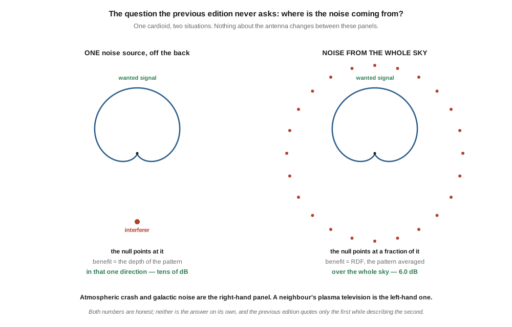
Against one dominant interferer the null is worth its full depth. A neighbour’s switching supply, a failing streetlight, a plasma television two houses away — put the null on it and the improvement really is tens of decibels, exactly as the chapter’s arithmetic says. In that case the depth of the pattern in that specific direction is the right measure.
Against noise arriving from everywhere, RDF governs completely, and the null’s depth is nearly irrelevant because the null covers a tiny fraction of the sky.
The authority for this is explicit. W8JI, whose RDF comparison §6 uses, states the conditions under which RDF “will be an almost perfect indicator of what you can expect from your antenna”:
- Noise is not from the same general direction as the desired signal
- Noise field strength is not greater than the ratio of peak antenna response to depth of the pattern in the direction of noise
- Noise is not coming from within the antenna’s nearfield or Fresnel zone
🔴 The previous edition draws none of these distinctions. It quotes a single-direction number and describes an all-directions benefit, with nothing in between to tell the reader which situation they are in.
⭐⭐ This dive has met that failure before, in the companion chapter. The transmitting loops dive found the same conflation in its own seed — a magnetic loop credited with broad noise rejection when what it actually has is a rotatable null, worth far more than 10 dB against one source and worth nothing at all against distributed noise. Both loop chapters make the same mistake, and neither separates the two cases. ⚠ They are not the same defect in detail — that one misattributed the mechanism, this one misapplies the metric — but the missing distinction is identical, and it is the single most useful idea either chapter lacks.
1.5.1 And the sky is not quiet
Rebuilding the noise table turned up something that settles which case is the common one, and the chapter does not mention it.
Setting the quiet-rural and galactic curves equal:
53.6 − 28.6 log f = 52.0 − 23.0 log f → log f = 1.6 / 5.6 = 0.2857 → f = 1.93 MHz
⭐⭐ Above 1.93 MHz — which is to say across the entire HF spectrum bar the very bottom of 160 metres — a quiet rural station’s noise floor is set by the galaxy, not by human activity. At 40 metres a quiet site sees 29.4 dB of man-made noise against 32.6 dB of galactic; at 20 metres, 20.8 against 25.6.
⭐⭐⭐ And galactic noise is the textbook distributed source. It arrives from the whole sky, it cannot be nulled, and no amount of front-to-back ratio touches it. So for the operator who has done the hard work of finding a quiet site — the operator most likely to be reading this chapter — the case where RDF governs completely is not a special case. It is the normal one.
⚠ The opposite holds in town, where a handful of local sources dominate and the null is the whole point. Which figure of merit applies depends on where you live, and that is the sentence the chapter needed and does not contain.
1.6 What the numbers really are
With the right quantity identified, the chapter’s performance tables can be checked against published values.
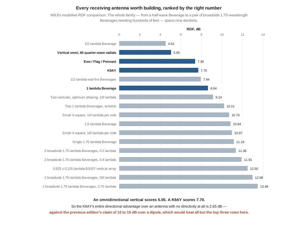
W8JI’s modelled comparison covers seventeen receiving antennas:
Table 4 — W8JI's modelled comparison covers seventeen receiving antennas
| antenna | RDF |
|---|---|
| 1/2 λ Beverage | 4.52 |
| Vertical omni, 60 quarter-wave radials | 5.05 |
| Ewe / Flag / Pennant | 7.39 |
| K9AY | 7.70 |
| 1/2 λ end-fire Beverages | 7.94 |
| 1 λ Beverage | 8.64 |
| Two verticals, optimum phasing, 1/8 λ | 9.14 |
| Two 1 λ Beverages, echelon | 10.21 |
| Small 4-square, 1/4 λ per side | 10.70 |
| 1.5 λ Beverage | 10.84 |
| Single 1.75 λ Beverage | 11.16 |
| 2 broadside 1.75 λ Beverages, 0.75 λ | 13.48 |
⭐⭐⭐ The second row settles the chapter’s claims. An omnidirectional vertical — an antenna with no azimuthal directivity whatsoever — scores 5.05 dB. A K9AY scores 7.70. The K9AY’s entire directional advantage over an antenna that points nowhere is 2.65 dB.
Against that, the previous edition’s tables claim:
Table 5 — Against that, the previous edition's tables claim
| the chapter’s claim | antenna |
|---|---|
| ”SNR improvement vs dipole: 8–15 dB” | 1 λ beverage |
| ”SNR improvement vs dipole: 10–15 dB” | K9AY |
| ”SNR improvement vs dipole: 8–12 dB” | flag |
🔴 The claimed improvement for a K9AY in a thirty-foot footprint exceeds the absolute RDF of every antenna in the table but the top three — and those need hundreds of feet of real estate. A figure of 15 dB would put a small terminated loop above a pair of broadside 1.75 λ beverages spaced three-quarters of a wavelength apart. The whole seventeen-antenna family spans nine decibels, from 4.52 to 13.48.
1.6.1 Checking the check
Two independent tests say the RDF figures used throughout this volume are computed correctly.
⭐ A free-space half-wave dipole returns an RDF of 2.15 dB. Averaged over the full sphere RDF is directivity, and a half-wave dipole’s directivity is 2.15 dBi. Reproducing that to two decimal places says the numerical integration is sound.
⭐⭐ And a beverage modelled with nothing but the travelling-wave formula lands within about a decibel of W8JI’s figure at one wavelength — 7.60 against his 8.64 — from an expression with no ground model in it at all.
⚠⚠ That agreement is a check, not a licence. At half a wavelength the same model reads 0.8 dB high, and at 1.5 λ it reads 1.7 dB low; short beverages depend most on the lossy ground the formula omits. Where a published figure exists, this dive quotes the published figure. The computations here exist to test the chapter’s reasoning, not to stand in for a NEC model that was run properly.
⚠ One gap is left open rather than papered over. The chapter compares everything to “a dipole”, and no dipole appears in W8JI’s table. A free-space dipole’s 2.15 dB is not the right reference for a low horizontal dipole over real ground, whose pattern the ground reflection pushes upward. The comparisons in this volume are therefore made against the omnidirectional vertical, which is in the table and is a fair stand-in for “an ordinary non-directional antenna”. ▶ Establishing the dipole’s RDF properly is recorded as owed work.
1.7 What follows for choosing an antenna
Three things follow, and none of them is “receiving antennas do not work.”
First, the achievable range is narrow and the whole family sits close together. From a half-wave beverage to a serious phased array is nine decibels. Among the small terminated loops that fit on a suburban lot — flag, pennant, EWE, K9AY, all between 7.39 and 7.70 — there is a third of a decibel. ⭐ Choose among them on footprint, cost and how easily they steer, because their RDF is effectively identical. Vol 3 takes that up.
Second, the step that actually buys performance is going from one antenna to two. Two verticals optimally phased score 9.14 against a single vertical’s 5.05; two beverages in echelon score 10.21 against one beverage’s 8.64. ⭐ Combining antennas moves the number more than perfecting any single one, which is the argument for the phased arrays the chapter treats as an afterthought.
Third — and this is the practical heart of it — the null and the RDF are two separate purchases, and you should know which one you are making. If a single identifiable noise source is ruining your reception, buy the null: aim it, and the improvement will be dramatic and will look nothing like 2.65 dB. If you are fighting atmospheric crash on 160 metres at a quiet site, buy the RDF, expect a few decibels, and understand that a few decibels at the right moment is the difference between copying a signal and not copying it.
⚠⚠ Do not read this volume as deflationary. Two or three decibels of RDF is a real improvement, obtained without a tower, on an antenna costing fifty dollars in wire — and the operators who put these antennas up are not wrong about hearing better. The correction is to the arithmetic and to the expectation, not to the practice.
1.8 Where this volume hands off
The previous edition’s framework is right and its measurement is wrong. Loss really is free when external noise sets the floor; termination really does buy a null by killing the reflected wave; the receiver’s noise figure really is irrelevant through HF, though by fifty-five decibels rather than the hundred-plus claimed. What does not survive is front-to-back ratio as the figure of merit — because a perfect null makes it infinite while the benefit it stands in for is capped a shade above six decibels, and because the two do not rank antennas in the same order.
The question the chapter never asks is where the noise is coming from. Against one interferer the null is worth everything the chapter says. Against the whole sky it is worth its RDF, and at a quiet site above 1.93 MHz the sky is exactly what you are listening to, because the floor is galactic.
From here:
- Vol 2 takes the beverage, whose polarisation the previous edition states backwards and whose operating mechanism — wave tilt — it never mentions.
- Vol 3 takes the small terminated loops, where §7’s finding that a third of a decibel separates them decides how to choose.
- Vol 4 takes active loops and ferrite rods, where the amplifier’s noise figure re-enters the argument §2 removed it from.
- Vol 5 builds and measures one, and surveys a market in which two of the manufacturers this chapter recommends have stopped trading.
- The transmitting loops dive, Vol 4 is the companion treatment of the same conflation, and the place where a rotatable null was first separated from broad noise rejection in this hub.
- Fixed vertical monopoles, Vol 1 is the omnidirectional baseline §6 measures against.
Three things are owed. A dipole’s RDF over real ground, which is the comparison the chapter makes and this volume could not close. An independent accuracy review — no volume in this dive has had one, and every previous dive’s fresh-reviewer pass found real defects in every volume. And a measurement: nothing here is first-hand, and Vol 5 is written as the place to fix that.
1.9 Resources
- Recommendation ITU-R P.372-13, Radio noise (September 2016) — the source of every noise figure in §2, including Table 1’s constants and the stated validity range, read directly from the Recommendation rather than from a summary.
- W8JI, Comparison of Beverage antenna, magnetic loop antenna, and phased vertical receiving antennas — the seventeen-antenna RDF table in §6 and the three validity conditions quoted in §5.
- ON4UN, Low-Band DXing — the standard reference for low-band receiving practice, and the work that put RDF into general amateur use.
- Gary Breed, K9AY, original 1995 description of the terminated loop that carries his call — taken up in Vol 3.
- H. H. Beverage, C. W. Rice and E. W. Kellogg, The Wave Antenna: A New Type of Highly Directive Antenna, AIEE 1923 — the primary source for Vol 2.
- Transmitting loops, Vol 4 — the rotatable null against distributed noise, and the near-field wave-impedance mechanism Vol 4 inherits.
- Transmitting loops, Vol 1 — why a small loop radiates at all, and the Chu limit stated correctly.
- Fixed vertical monopoles, Vol 1 — the vertical whose 5.05 dB RDF is this volume’s baseline.
- Baluns and ununs, Vol 4 — the 9:1 and 16:1 transformers every terminated antenna in this dive is fed through.
Comments (0)