Receive-Only Loops & Specialty Receive Antennas · Volume 4
Active Loops and Ferrite Rods
The chapter ranks eight products by the one parameter that barely moves the answer, the budget loop's measured noise figure is four times its claim and still is not what is wrong with it, two of the manufacturers recommended have stopped trading, and a rod's shape matters more than the ferrite in it
4.1 About this volume
The three previous volumes covered antennas that get their directivity from geometry and pay for it in land. This one covers the antennas that give up directivity almost entirely and buy their way back with an amplifier: the active loop, a metre or so across with a low-noise amplifier at its feedpoint, and its small relative the ferrite rod.
They are the apartment-dweller’s answer, and the chapter is right that they work. It is wrong about why, and about how to choose one.
The chapter ranks eight active loops on a single figure of merit: the LNA’s noise figure. §2 shows that noise figure is very nearly irrelevant here, for exactly the reason Vol 1 gave for the receiver — external noise sits twenty to fifty-five decibels above it through the whole of HF. ⭐⭐ This is the second time in this dive that the chapter has ranked antennas on a quantity that barely moves the answer. Vol 1 found it doing the same thing with front-to-back ratio.
The measured figure for the budget loop it recommends is four times the one it prints — 12 dB against 3 dB — and that is still not what is wrong with it. §4.
What actually separates a good active loop from a bad one is dynamic range, because an amplifier bolted to an antenna has no preselection in front of it and sees every broadcast transmitter within range at once. §3. The chapter’s table contains no intercept point, no compression point, and no mention of overload for any product.
And the survey has the same trouble as the last two. Two of the eight manufacturers listed have stopped trading, one product is credited to a person who did not design it, one entry is a whip filed among the loops, and the chapter contradicts itself on a price. §5.
⚠ The framing in §2.4 is also inverted, and §2 shows why: the chapter says the active approach suits “very weak DX” and a “moderate” local noise level. The arithmetic says an active loop is easiest exactly where the noise is worst.
4.2 The budget an active loop works inside
Vol 1 established the governing fact: on HF, external noise is far above a receiver’s own. The same argument decides everything about an active antenna, and it is worth stating as a single condition.
External noise dominates the system when
Fa − L_antenna − NF > margin
where Fa is the external noise figure from ITU-R P.372, NF is the amplifier’s noise figure, and L_antenna is everything between the arriving field and the amplifier input — the small element’s limited capture, the mismatch between a metre of wire loop and an amplifier input, and ohmic loss.
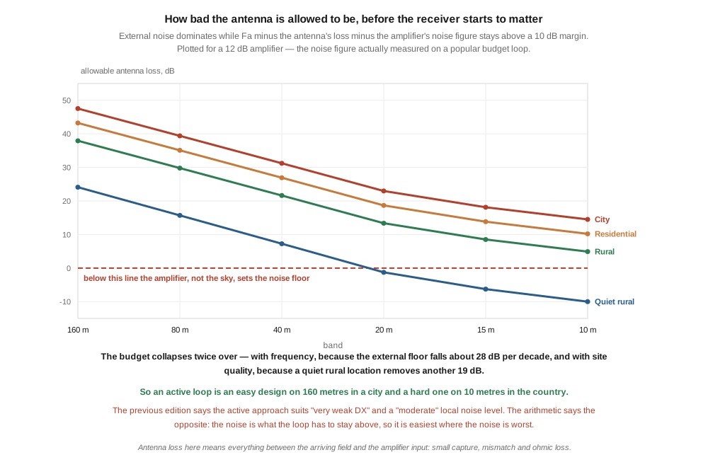
Rearranged, that is a loss budget: how bad the antenna is allowed to be before the amplifier, rather than the sky, sets the noise floor. Taking 10 dB as “comfortably dominant”, and a 12 dB amplifier:
Table 1 — Rearranged, that is a loss budget: how bad the antenna is allowed to be before the amplifier, rather than the sky, sets the noise floor. Taking 10 dB as "comfortably dominant", and a 12 dB amplifier
| band | city | residential | rural | quiet rural |
|---|---|---|---|---|
| 160 m | 47.5 | 43.2 | 37.9 | 24.1 |
| 80 m | 39.4 | 35.1 | 29.8 | 15.7 |
| 40 m | 31.2 | 26.9 | 21.6 | 7.3 |
| 20 m | 23.0 | 18.7 | 13.4 | −1.3 |
| 15 m | 18.1 | 13.8 | 8.5 | −6.3 |
| 10 m | 14.5 | 10.2 | 4.9 | −10.0 |
⭐⭐⭐ The budget collapses twice over. With frequency, because the external floor falls about 28 dB per decade; and with site quality, because moving from a city to a quiet rural location removes another nineteen decibels of the very thing the antenna is trying to stay above.
On 160 metres in a city an active loop can afford to be forty-seven decibels lossy and nobody will notice. On 10 metres at a genuinely quiet site there is no budget at all: the amplifier is the noise floor, and a better antenna is the only fix.
🔴 This inverts the chapter’s guidance. §2.4 says the active approach is right when “the signal of interest is below the receiver’s sensitivity threshold (very weak DX)” and when “the local noise level is moderate (allowing the LNA to lift signal above receiver noise…)”.
Neither holds. Weak signals are not the criterion — the noise is, because the noise is what has to stay above the amplifier. And a moderate noise level is not an enabling condition but a constraint: the quieter the site, the harder the antenna has to work. An active loop is easiest in exactly the environment its owner is usually trying to escape.
⚠ Two honest limits on this table. The 10 dB margin is a convention, not a standard — at 3 dB the antenna is degrading the system by half a decibel, which many operators would accept. And L_antenna is a lumped quantity that this dive does not compute from geometry, because an active loop is deliberately not conjugate-matched and the amplifier’s input impedance is part of the antenna. The table says how much loss is affordable, not how much a given loop has. ▶ Measuring that is recorded as owed work.
4.3 What actually separates one from another
If noise figure is not the discriminator, something is. The clearest statement comes from Martin G8JNJ, who reverse-engineered and measured one of the products the chapter recommends:
An active antenna has a finite S/N ratio. This is defined by the amount of signal that can be intercepted by the actual antenna element, any mismatch losses between the antenna and amplifier, the noise figure and gain of the amplifier and the level of signals that can be amplified before distortion occurs.
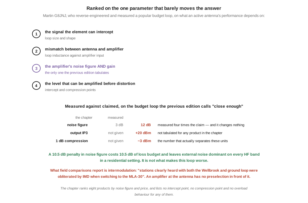
Four terms. The chapter’s product table has columns for frequency range, LNA noise figure and price — part of the third term, and none of the first, second or fourth.
⭐⭐⭐ The fourth is the one that decides. An LNA at the antenna has nothing in front of it. A receiver has a preselector, or at minimum a band-pass filter; an active loop’s amplifier sees the entire spectrum from the broadcast band upward, simultaneously, and has to amplify all of it linearly. On a good site that is a modest requirement. Within a few miles of a medium-wave transmitter it is the whole design problem.
And this is what field comparisons actually report. On the budget loop the chapter calls “close enough”:
had a very serious issue with IMD where stations clearly heard with both the Wellbrook and ground loop were obliterated by IMD when switching to the MLA-30
⭐ “Obliterated” is a dynamic-range failure, not a sensitivity failure. A signal that is present on one antenna and absent on another, at the same location and the same moment, has not been lost in noise — it has been buried under intermodulation products manufactured inside the amplifier.
⚠ The first two terms matter too, and the chapter omits them as well. G8JNJ on what a good design requires:
the loop has to be made from a large diameter conductor or flat strip in order to minimise the overall loop inductance
⭐ That is the same conductor-size argument the transmitting loops dive makes for a different reason. There, fat tubing lowers loss resistance; here, it lowers inductance so the loop can be matched to an amplifier across a decade of frequency. Both dives arrive at “use the fattest conductor you can” from opposite directions.
4.4 The measured numbers
§8.2 lists the MLA-30+ at NF 3 dB. G8JNJ measured the amplifier:
Table 2 — §8.2 lists the MLA-30+ at NF 3 dB. G8JNJ measured the amplifier
| the chapter | measured | |
|---|---|---|
| noise figure | 3 dB | 12 dB |
| output IP3 | not given | +20 dBm |
| 1 dB compression | not given | −3 dBm |
and identified the part as “a Texas TL592B two stage video amplifier which isn’t that great for this application”, with “the impedance match of the loop to low pass filter … very wrong, resulting in a very poor amplitude/frequency response” and “a sweet spot centered around 6MHz”.
🔴 The noise figure is four times the printed claim. And now the useful part:
Table 3 — 🔴 The noise figure is four times the printed claim. And now the useful part
| band | residential Fa | budget at NF 1.5 | budget at NF 12 | external noise still dominant? |
|---|---|---|---|---|
| 160 m | 65.2 | 53.7 | 43.2 | yes |
| 80 m | 57.1 | 45.6 | 35.1 | yes |
| 40 m | 48.9 | 37.4 | 26.9 | yes |
| 20 m | 40.7 | 29.2 | 18.7 | yes |
| 15 m | 35.8 | 24.3 | 13.8 | yes |
| 10 m | 32.2 | 20.7 | 10.2 | yes |
⭐⭐ A 10.5 dB penalty in noise figure costs 10.5 dB of loss budget and changes nothing about whether external noise dominates, anywhere in a residential setting across the whole of HF.
⭐⭐⭐ So the chapter’s headline specification is wrong by a factor of four, and correcting it does not change the recommendation. That is the sharpest possible demonstration that it is the wrong column: an error large enough to be embarrassing, in a parameter with almost no leverage on the outcome. Meanwhile the two numbers that would separate these products — the intercept and compression points — appear nowhere in the chapter for any of the eight.
⚠⚠ This is not a verdict that the budget loop is useless. The same reviews that report the intermodulation also report that it does the job it is bought for:
If you are an SDR user or have a portable shortwave radio and find your current reception is plagued by local electrical noise, the MLA-30+ is a low-risk, high-reward upgrade.
⭐ Both things are true, and they are consistent with §2: in a noisy urban location the budget is enormous, the amplifier’s shortcomings are buried, and a fifty-dollar loop transforms reception. Move it to a quiet site or point it at a strong local transmitter and the same unit falls apart. The chapter’s error is not recommending it; it is recommending it on a number that does not predict where it will fail.
4.5 Buying one: a dated survey
Checked against live pages on 3 August 2026. Products that could not be found, and manufacturers that no longer exist, are listed as such.
🔴🔴 Wellbrook Communications ceased trading at the end of April 2023. Andy Ikin, who founded it and designed the loops, died on 25 October 2024. The chapter lists two Wellbrook models as current, at $400 and $600, and calls the ALA1530LN “the canonical reference active loop in the amateur SDR community” — which it was, and which is exactly why the entry needs correcting rather than deleting.
⭐⭐ And there is a buyer hazard that must be carried. Ikin tried to sell the business on retirement and could not, because a Chinese company had hijacked the trademarks. The Wellbrook name on a unit sold today is not evidence that Wellbrook made it.
⭐ This is the third dive in this program to find a dead manufacturer sold as current, after MFJ appeared as current in both the antenna tuners dive and the transmitting loops dive. ▶ The rule is now explicit: check whether a company still trades before pricing its products.
Table 4 — 5. Buying one: a dated survey
| the chapter’s entry | status, 3 August 2026 |
|---|---|
| Wellbrook ALA1530LN, $400 | 🔴 manufacturer ceased trading April 2023; trademarks hijacked |
| Wellbrook ALA1530LFL, $600 | 🔴 same, and the designation does not match Wellbrook’s own naming |
| LZ1AQ kit, $300 | 🔴 designer misattributed — see below |
| Bonito MegActiv MA-305, $350 | ⚠ real model is the MA305FT at US$257.95 — 36 % high. And it is a 22 cm whip, not a loop |
| Bonito MegaLoop FX, $480 | ✅ real, US$505.95. This one is a loop |
| MFJ-1886, $250 | 🔴 MFJ ceased manufacturing 17 May 2024 |
| MLA-30+, $50–80 | ✅ price stands; 🔴 but see §4 |
🔴 §8.4 credits the LZ1AQ active loop to “Joel Wallman”. It was designed by Chavdar Levkov, a Bulgarian amateur — LZ is the Bulgarian prefix, which the callsign itself gives away. His commercial product is the AAA-1C Active Antenna Amplifier, not the chapter’s “LZ1AQ Type C”.
⭐ This is the fourth dive in this program with a fabricated attribution, after the invented Cebik rows in the yagi dive and two products in the transmitting loops dive that could not be found to exist. A named individual credited with someone else’s work is the most consequential form of it, because it is the hardest for a reader to check and the most unfair to the person who did the work.
🔴 And the chapter contradicts itself on price nine lines apart: the §8.2 table lists the LZ1AQ at “$300 (kit)” while §8.4 says “The DIY LZ1AQ kit costs $50 in parts”.
⚠ One entry is in the wrong table entirely. The Bonito MegActiv MA305FT has a 22 cm radiating element — it is an active whip, and it belongs beside the ferrite rod in §6 rather than among the loops. Its pattern, its noise behaviour and its susceptibility to local electric-field noise are all different from a loop’s. Listing it as an active loop invites exactly the comparison it will lose.
4.6 The ferrite rod
The chapter’s §7 is short and mostly right: a ferrite rod is the AM broadcast antenna, it is compact, it has a figure-of-eight pattern with deep nulls, and it is not a transmitting antenna. All true.
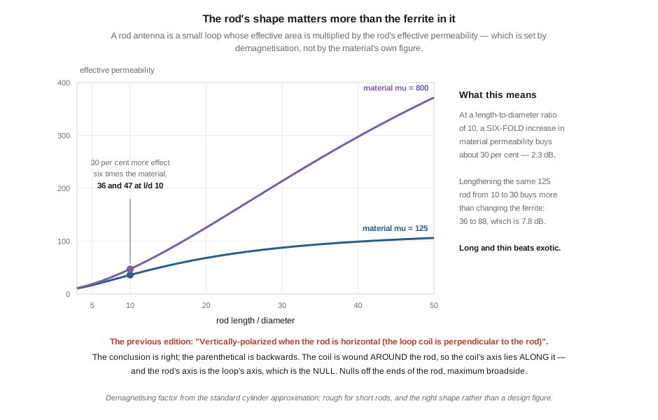
The physics worth adding is why rods are the shape they are. A rod antenna is a small loop whose effective height is multiplied by the rod’s effective permeability:
h_eff = 2π N A μ_rod / λ
and μ_rod is not the material’s μ_i. It is set by demagnetisation — the rod’s own ends produce a field opposing the one you are trying to concentrate — and therefore by the length-to-diameter ratio:
Table 5 — and μrod is not the material's μi. It is set by demagnetisation — the rod's own ends produce a field opposing the one you are trying to concentrate — and therefore by the length-to-diameter ratio
| rod length / diameter | μ_rod, material μ = 125 | μ_rod, material μ = 800 |
|---|---|---|
| 5 | 17 | 19 |
| 10 | 36 | 47 |
| 20 | 68 | 126 |
| 30 | 88 | 213 |
| 50 | 106 | 372 |
⭐⭐ At a length-to-diameter ratio of 10, a six-fold increase in material permeability buys about thirty per cent — 2.3 decibels. Lengthening the same 125-material rod from a ratio of 10 to 30 buys more than changing the ferrite does: 36 to 88, which is 7.8 dB.
⭐ That is why every AM radio rod is long and thin, and why “higher permeability ferrite” is the weaker of the two upgrade paths. It also explains why the rods get longer rather than fatter in better receivers.
⚠ The demagnetising factor here comes from the standard cylinder approximation and is rough for short rods. It is the right shape of answer, not a design figure.
4.6.1 One parenthetical to fix
§7.2 says the rod is “Vertically-polarized when the rod is horizontal (the loop coil is perpendicular to the rod)”.
⭐ The conclusion is right — a horizontal rod does respond to vertically polarised waves. The parenthetical is backwards. The coil is wound around the rod, so the coil’s axis lies along the rod. And that matters, because the coil’s axis is the loop’s axis, which is the null direction: a rod antenna nulls off its ends and hears best broadside. That is the fact an operator uses when rotating a portable radio to kill a local station, and the chapter’s parenthetical would have them turn it ninety degrees the wrong way.
4.7 What the chapter gets right
⚠ Over-correction is a named failure mode in this program, and §7 and §8 of the chapter are largely sound.
§8.1’s description of the active-loop concept is accurate: a small loop, an LNA at the feedpoint, a bias tee at the shack end, 50 Ω out. That is the architecture, and it is the right one.
§2.4’s passive-versus-active split is sound — the passive answer when space allows, the active answer when it does not — even though the criteria attached to it need the correction in §2.
⭐⭐ And §8.3’s noise claim is right, and was right for the right reason. The chapter says an active loop has “6–10 dB less local-noise pickup than a comparable-size wire antenna”. Vol 1 noted that the transmitting loops dive found the same magnitude attached to a polarisation mechanism that could not produce it — but here it is attached to loop-versus-wire pickup, which is the near-field wave impedance effect that dive identified as the real one. A magnetic antenna is under-coupled to the high-impedance near field of a local electric-field source. The number survives; only the transmit chapter’s explanation did not. ⚠ Do not import that correction here.
⭐ §8.3’s pattern statement is also correct — “figure-8 in the plane of the loop, deep nulls perpendicular” — which is worth noting because the transmitting loops chapter got the same fact exactly backwards. The receive chapter is the reliable one on small-loop patterns.
⚠ §8.3’s “equivalent to a 60-foot wire antenna at the same height” is unsourced and depends on far too many unstated variables to check. Flagged rather than corrected.
4.8 Where this volume hands off
An active loop is an amplifier with an antenna attached, and the chapter picks amplifiers by the wrong specification. Noise figure barely matters, for exactly the reason Vol 1 gave about receivers: on HF there is between ten and fifty decibels of external noise sitting above it, and the whole design problem is staying above the amplifier, not below the signal. The budget for doing that collapses with frequency and with site quality, which makes an active loop an easy design in a noisy city on 160 metres and a hard one at a quiet rural site on 10.
What separates these products is dynamic range, because an amplifier at the antenna has no preselection and sees everything at once. The chapter’s own recommended budget unit demonstrates it: its measured noise figure is four times the printed claim, correcting it changes nothing, and the failure people actually report is intermodulation.
From here:
- Vol 5 builds one and measures it, and owes this volume two numbers: the antenna’s real contribution to
L_antenna, and an overload test. - Vol 3 is where the preamplifier arithmetic started — a K9AY needs about 15 dB of gain, and the chapter’s undersized version would need about 34.
- Vol 1 is the noise regime and the figure-of-merit argument this volume applies for the second time.
- Transmitting loops, Vol 4 is the near-field mechanism behind §7’s confirmed noise claim.
- Transmitting loops, Vol 1 is the other dive that concludes “use the fattest conductor you can”, for a different reason.
Three things are owed. A measurement of L_antenna for a real loop, which would turn §2’s budget from a constraint into a design check. An overload test — a two-tone intermodulation measurement is the thing that would actually rank these products, and none of the published figures for seven of the eight exist. And an independent accuracy review, which no volume in this dive has had.
4.9 Resources
- Martin, G8JNJ, reverse-engineering measurements of the MLA-30 loop amplifier, reported via rtl-sdr.com — the four-term definition in §3, and the noise figure, OIP3 and compression point in §4.
- Recommendation ITU-R P.372-13, Radio noise — the external noise floor underlying §2’s budget, as rebuilt in Vol 1.
- The SWLing Post and rtl-sdr.com MLA-30 comparison reports — the intermodulation observations quoted in §3 and §4.
- Bonito product pages and dealer listings — the MA305FT and MegaLoop FX specifications and prices in §5.
- Wellbrook Communications closure reports, April 2023, and subsequent notices — §5.
- LZ1AQ (Chavdar Levkov), active antenna amplifier documentation — the correct attribution and the AAA-1C designation in §5.
- Vol 1 — the noise regime, and the first instance of the wrong-figure-of-merit problem.
- Vol 3 — the preamplifier requirement for a terminated loop.
- Transmitting loops, Vol 4 — near-field wave impedance, the mechanism behind the 6–10 dB claim.
- Transmitting loops, Vol 1 — conductor size, from the loss side.
- Antenna tuners, Vol 5 — the MFJ manufacturing date, and the survey standard this section tries to meet.
Comments (0)