Receive-Only Loops & Specialty Receive Antennas · Volume 3
Small Terminated Loops — K9AY, Flag, Pennant and EWE
One sentence from the designer settles three of the previous edition's errors at once, the direction is inverted by carrying a beverage convention into a family where it is reversed, the null is not where the chapter says it is, and the loop specified is a ninth of the published one
3.1 About this volume
Vol 2 covered the antenna that works brilliantly and needs three hundred feet of land. This volume covers the family that exists because most people do not have three hundred feet: the K9AY loop, the flag, the pennant and the EWE, all of which fit in a suburban garden and all of which give up a few decibels of RDF to do it.
The previous edition devotes three sections to them and gets the practical shape of the subject right — these are the small-lot answer, they are all terminated, they all give a cardioid, and the K9AY’s switchable four directions are its signature. Underneath that, four things need correcting, and one sentence from the man who designed the K9AY settles three of them together.
The direction is inverted. §4.1 says the K9AY’s “gain peaks in the direction toward the termination, deep null in the direction toward the feedpoint.” It is the other way round — and §4 shows the mistake is not a slip but a specific, explicable one: a beverage and a terminated loop use opposite conventions, and the chapter describes the beverage first.
The EWE is drawn as the wrong antenna and the flag’s dimensions are transposed. §3 fixes both, and both fall out of the same sentence about what these antennas are.
The K9AY specified is a ninth of the published one. §5 works out what that costs, using the designer’s own statement that signal follows enclosed area.
And the null is not where the chapter puts it. §6: the K9AY’s null sits at 35 to 45 degrees of elevation, by deliberate design, and the chapter never mentions elevation at all. That single fact changes what the antenna is for.
⚠ The chapter’s practical advice, though, is mostly sound, and §7 and §8 are largely confirmations. Where it is wrong it is wrong about mechanism and geometry, not about whether these antennas are worth building.
3.2 What these antennas actually are
The chapter treats the K9AY, flag, pennant and EWE as four separate designs with four separate descriptions. Gary Breed, who designed the K9AY, treats them as one thing, and his sentence is the most useful in the whole subject:
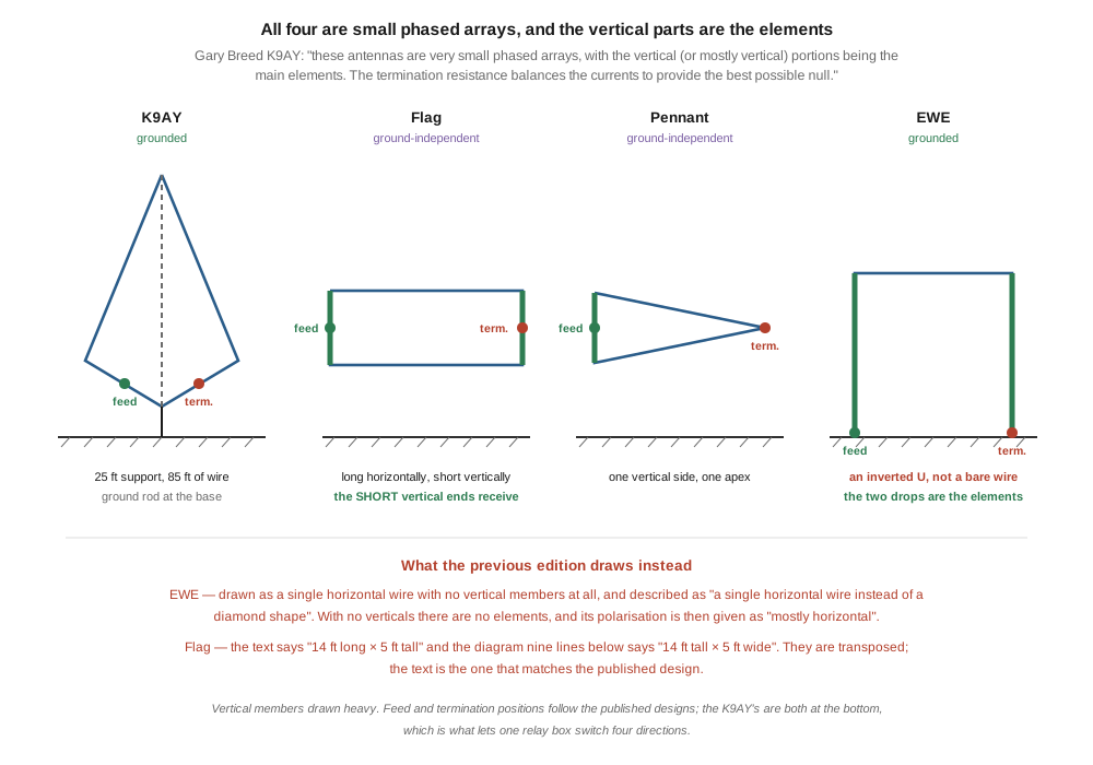
The EWE, Pennant, Flag and others all operate using the same principle as the K9AY Loop, and they all provide a cardioid pattern with one deep null. In simplest terms, these antennas are very small phased arrays, with the vertical (or mostly vertical) portions being the main elements. The termination resistance balances the currents to provide the best possible null.
⭐⭐⭐ The vertical portions are the elements. Everything else is interconnection.
That is not a nicety. It settles three separate questions the chapter gets wrong:
- The EWE must have vertical members. An antenna with no vertical portions has no elements. §3.
- The family is vertically polarised, because its elements are vertical. The chapter gives the EWE as “mostly horizontal” — the same error Vol 2 found on the beverage, for the same reason: reading polarisation off the longest wire.
- The flag is a horizontal rectangle whose short vertical sides do the receiving, which settles the transposed dimensions in §3.
⭐ Breed also warns off the framing the chapter reaches for. The seed’s §2 leans on E-field and H-field language throughout, and Breed explicitly deprecates it:
It is also possible to explain the loop’s behavior in terms of its response to the E-field and H-field components of the arriving wave, but this is more complicated than necessary!
Two vertical elements, spaced a short distance apart, with a resistor setting the relative current — that is a phased array with a cardioid pattern, and it needs no field decomposition to understand.
3.3 Two of them are drawn wrong
3.3.1 The EWE
§6.1 draws the EWE as a single horizontal wire between two points, and §6.2 describes it as “simpler than a K9AY (single horizontal wire instead of a diamond shape).”
🔴 An EWE is an inverted U. A horizontal top wire, and two vertical drops at the ends — one to the feed transformer and its ground, the other to the termination and its ground. Per §2, those two drops are the elements. As drawn in the chapter, with no verticals at all, the antenna has nothing to receive with.
⭐ The chapter’s own text half-knows. §6.1 says the EWE “optionally uses ground rods at both ends”, which is meaningless for a wire floating between two insulators and essential for an inverted U. The ground rods are not optional and they are not an afterthought; they complete the two elements.
⚠ And the polarisation error follows directly. Once the verticals are missing, “mostly horizontal” is the only description the drawing supports.
3.3.2 The flag
§5.1’s text says the flag is “~14 ft × 5 ft (e.g. 14 ft long × 5 ft tall, vertical orientation)”. Its diagram, nine lines below, is labelled “14 ft tall × 5 ft wide”.
🔴 The two are transposed, and per §2 the text is the one that matches the published design: a flag is longer horizontally than it is tall, and its short vertical ends are the elements. The horizontal runs set the spacing between them.
⭐ This is the third dive running in which a drawing and its prose disagree — after the antenna-tuners schematics and the transmitting-loops pattern diagram. ▶ The rule this program keeps relearning: verify a drawing by constructing the thing it depicts. Here, constructing it means asking which parts are the elements, and the answer immediately picks the text over the diagram.
3.4 Which way does it point?
§4.1 states the K9AY’s pattern as:
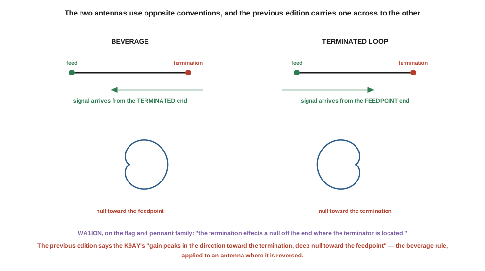
The K9AY’s cardioid pattern: gain peaks in the direction toward the termination, deep null in the direction toward the feedpoint.
🔴 That is inverted. The published statement for the family, from WA1ION’s work on flags and pennants:
The direction of expected nulls is the way you’re facing if standing at the receiver feedline side of the antenna and looking towards the termination. In other words, the termination effects a null off the end where the terminator is located, thereby producing a cardioid directional pick-up pattern.
Null toward the termination. Maximum toward the feedpoint.
⭐⭐⭐ And the diagnosis is specific rather than a shrug. On a beverage the wanted signal arrives from the terminated end — the wave travels along the wire toward the feedpoint, which is why Vol 2’s diagrams put the signal on the termination side. The chapter describes the beverage in §3 and the K9AY in §4, and carries the beverage’s convention across.
The two antennas are opposite, and reasoning by analogy from one to the other gives the wrong answer every time. They are opposite because they work differently: a beverage integrates a travelling wave along a wire pointed at the signal, while a terminated loop is a two-element phased array whose null direction is set by which element carries the resistor.
⚠ Practically it matters less than it looks, and more than it should. A K9AY installation is switched — Breed’s relay box swaps feed and termination to reverse the pattern — so an operator who has it backwards finds out in one over and presses the other button. But the chapter’s §4.3 table assigns compass directions to switch positions (“Loop 1, normal: NE”), and those assignments are exactly the thing that is now reversed.
⭐ Breed’s siting advice depends on getting it right, too:
if you are most interested in hearing Europe from the US, locate the loop Northeast of the transmitting antenna. When pointed toward Europe, the null will be in the direction of the transmitting antenna, reducing the pickup of re-radiated signals.
That only works if you know which end nulls.
3.5 How big, and the loop that is a ninth of the published one
§4.1 specifies:
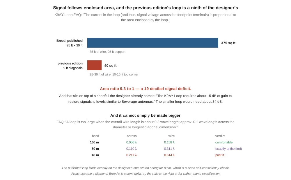
25–30 ft of wire in a diamond shape · Each diagonal of the diamond ~8–10 ft · Top corner ~10–15 ft above ground; bottom corner ~5 ft
Breed’s own build document specifies:
A single loop that will cover the 160 and 80 meter ham bands requires one 25-foot high support and 85 feet of wire.
and the K9AY FAQ gives the dimensions as “25 ft. height, +/− 15 ft. across”.
🔴 The chapter’s loop is roughly a third of the published one in linear dimensions, which makes it about a ninth in enclosed area:
Table 1 — 🔴 The chapter's loop is roughly a third of the published one in linear dimensions, which makes it about a ninth in enclosed area
| wire | height | width | enclosed area | |
|---|---|---|---|---|
| published | 85 ft | 25 ft | 30 ft | ~375 sq ft |
| the chapter | 25–30 ft | 10–15 ft | ~9 ft | ~40 sq ft |
And the FAQ says exactly what that costs:
The current in the loop (and thus, signal voltage across the feedpoint terminals) is proportional to the area enclosed by the loop.
⭐⭐ A 9.3-to-1 area ratio is a 19 decibel signal deficit — and it lands on top of a shortfall the designer already flags:
The K9AY Loop requires about 15 dB of gain to restore signals to levels similar to Beverage antennas.
So the chapter’s loop would need something like 34 dB of preamplification rather than 15, which is a different engineering problem: at that gain the preamplifier’s own noise figure and overload behaviour start to matter, and Vol 4 is where that argument lives.
⚠ The area figures assume a diamond and Breed’s shape is a semi-delta, so the ratio is the right order of magnitude rather than a specification. The conclusion does not depend on the third significant figure.
3.5.1 And it cannot simply be made bigger
The FAQ gives the ceiling:
A loop is too large when the overall wire length is about 0.3 wavelength; approx. 0.1 wavelength across the diameter or longest diagonal dimension.
Checked against the published loop:
Table 2 — Checked against the published loop
| band | 30 ft across | 85 ft of wire | verdict |
|---|---|---|---|
| 160 m | 0.056 λ | 0.158 λ | comfortable |
| 80 m | 0.110 λ | 0.311 λ | exactly at the limit |
| 40 m | 0.217 λ | 0.614 λ | past it |
⭐ Which is what the FAQ says about its own design — “The published dimensions … are right at the upper limit for operation in the 80 meter band” — so the designer’s numbers are self-consistent, and this is a clean check on both.
⭐⭐ And it is the same 0.1 λ criterion the transmitting loops dive carries for a small loop. That dive marks every chart above C/λ ≈ 0.1 as outside its model. The two loop dives share a size ceiling for the same underlying reason: past it the current is no longer uniform around the loop, and the simple picture stops describing the antenna.
3.6 The null is not on the horizon
The chapter describes the K9AY’s null purely in azimuth — “deep null in the direction toward the feedpoint” — and never mentions elevation. The designer chose the shape specifically to place it:
A semi-delta loop shape was chosen for two reasons — it is practical for a single tall support, and it places the null at an elevation of 35–45 degrees above the horizon.
and
The shape of the loop determines the vertical angle of the null.
⭐⭐ That changes what the antenna is for. A null at 35 to 45 degrees is aimed at high-angle arrivals — short-skip interference, nearby stations coming in off a single hop, and the high-angle component of local noise. It is not aimed at a station on the horizon. A DX signal at five or ten degrees is nowhere near the null, which is precisely the point: you want the null on the interference and the wanted signal outside it.
⭐ It also explains a number that would otherwise look disappointing. Vol 1 reported the K9AY’s published RDF as 7.70 dB, only 2.65 dB better than an omnidirectional vertical. Part of the reason is that the deepest part of the pattern is pointed at a band of sky rather than along the ground, so it removes less of the total noise arriving from everywhere.
⭐ And the angle is adjustable, which the chapter also omits. WA1ION on the family:
if this termination can be varied, the horizontal and vertical angular positioning of the best null can be “slewed” to some extent. Plus or minus 30 degrees of null bearing variation is often possible.
Breed ships eight termination values from 340 to 680 Ω on a front-panel switch for exactly this reason. ⚠ The chapter presents the termination as a single fixed value (470 Ω), which is inside that range and is a perfectly good starting point — but it presents a tuning control as a component specification.
3.7 Choosing between four antennas a third of a decibel apart
Vol 1 reported the published RDF figures:
Table 3 — [Vol 1](/receive-only-loops/vol-1/) reported the published RDF figures
| antenna | RDF |
|---|---|
| Ewe / Flag / Pennant | 7.39 dB |
| K9AY | 7.70 dB |
0.31 dB apart. On performance, this is not a choice at all — and the chapter’s ranking of them by front-to-back ratio and beamwidth is, per Vol 1, a ranking on the wrong axis.
⭐⭐ Breed supplies the discriminator that actually exists, and it is not performance:
The grounded design of the K9AY Loop has several advantages over ground-independent versions of the terminated loop (Pennant and Flag), including simpler switching, no feedline isolation problems, and greater signal capture for the same size loops.
So the real split in this family is:
Grounded — K9AY and EWE. Both need a ground rod, or radials if the soil is dry. In exchange: simpler switching, no feedline isolation problem, and more signal for the same size.
Ground-independent — flag and pennant. No ground connection at all, so they can go on a flat roof, a balcony, a fibreglass mast, or anywhere a ground rod cannot. The cost is that the feedline must be isolated, because without a ground reference the coax braid becomes part of the antenna.
⭐ That is a decision an operator can actually make, and it is about where the antenna is going rather than about a decibel. ⚠ It also flatly contradicts the chapter’s framing of the flag as “the only directional 80 m receive antenna option” for someone with a small outdoor space — the K9AY needs a 25-foot support and 30 feet of clearance, but the choice between them is site-determined, not performance-determined.
⚠ One chapter claim confirmed: “The pennant variant … has slightly cleaner pattern symmetry and slightly better F/B (~2 dB more).” The published RDF figures group all three of Ewe, Flag and Pennant at a single value, which is consistent with small differences that do not survive into the figure of merit. Not corrected; simply not a reason to choose.
3.8 The termination resistor
§2.3 gives the material advice:
Non-inductive wire-wound or metal-film resistors work; carbon-composition is poor (inductive at HF).
🔴 That is inverted, and it rejects the one family that is actually non-inductive. Published characteristics:
Table 4 — 🔴 That is inverted, and it rejects the one family that is actually non-inductive. Published characteristics
| type | inductance | RF suitability |
|---|---|---|
| carbon composition | ”are non-inductive”; “offer good high frequency performance" | "preferably chosen for RF termination” |
| metal film | trimmed “by having a spiral track cut through the resistive film — they can be extremely inductive!“ | poor unless serpentine-trimmed |
| wirewound | ”wound on a form, they have very high inductance" | "not used in audio and RF circuits”, except purpose-made non-inductive types |
The chapter recommends the two inductive families and rejects the non-inductive one.
⚠⚠ Two guards against over-correcting this.
First, the chapter’s “non-inductive wire-wound” qualifier is legitimate. Ayrton-Perry wound resistors are real, genuinely non-inductive, and entirely appropriate here. The chapter is not wrong to list them; it is wrong about carbon composition and about unqualified metal film.
Second, carbon composition has a real defect — just not the stated one. It absorbs moisture and drifts in value. ⭐⭐ And that matters more here than in almost any other application, which is the actual engineering content of this section: per §6, both the depth of the null and its angle depend on holding the termination value. A resistor that wanders with humidity, in a box outdoors, degrades the single property the antenna exists for.
⭐ Which is a third argument for Breed’s switched, adjustable termination rather than a soldered-in part — alongside the soil dependence and the null slewing. If the value can be trimmed from the shack, drift stops being a failure and becomes a knob.
⚠ The chapter’s power rating is also generous. It specifies “2–5 W” on the grounds that the resistor “dissipates only receive-level energy” — which is true, and receive-level energy is measured in picowatts. A quarter-watt part is thermally fine. The reason to fit something larger is mechanical robustness and, at a station with a nearby transmitter, induced power from the transmit antenna. Right recommendation, wrong reason.
3.9 Where this volume hands off
Four antennas, one principle, and a third of a decibel between them. The chapter has the practical shape right — these are the small-lot answer, the K9AY’s switched four directions are its signature, and the family is worth building. What it gets wrong is what the antennas are made of and which way they face.
Breed’s sentence does most of the work: these are very small phased arrays whose vertical portions are the elements. From that, the EWE has to be an inverted U, the flag has to be longer than it is tall, and the whole family has to be vertically polarised. The direction is inverted because a beverage’s convention is the opposite and the chapter describes the beverage first. The specified K9AY is a ninth of the published one, at a cost of some nineteen decibels of signal, on an antenna that already needs fifteen decibels of gain. And the null the chapter places on the horizon is by deliberate design at 35 to 45 degrees of elevation, which is what the antenna is actually for.
From here:
- Vol 4 takes the active loops, where §5’s preamplifier arithmetic becomes the subject and the amplifier’s noise figure re-enters the argument Vol 1 removed it from.
- Vol 5 builds and measures one, and owes this volume a termination sweep — the null depth against termination value is the measurement that would settle §6 and §8 together.
- Vol 2 is the antenna these replace, and the source of the direction convention that trapped the chapter.
- Vol 1 is where the RDF figures and the two noise cases come from.
- Transmitting loops, Vol 1 shares the 0.1 λ size ceiling in §5, for the same physical reason.
- Baluns and ununs, Vol 4 is the 9:1 and 16:1 transformer at the feed point.
Three things are owed. A null-depth measurement against termination value, which §6 and §8 both point at and neither can supply. The 1995 date the chapter gives for the K9AY, which is unsourced — the QST paper is “The K9AY Terminated Loop — A Compact, Directional Receiving Antenna”, September 1997, and the design may or may not predate it. And an independent accuracy review, which no volume in this dive has had.
3.10 Resources
- Gary Breed, K9AY, How to Build the K9AY Loop Receiving Antenna, AY Technologies — the phased-array principle in §2, the dimensions and wire length in §5, the preamplifier figure, the siting advice in §4 and the grounded-versus-ground-independent comparison in §7.
- K9AY Loop FAQ, k9ay.com — the size ceiling, the termination range, the null’s elevation angle in §6, and the statement that signal follows enclosed area.
- Gary Breed, K9AY, “The K9AY Terminated Loop — A Compact, Directional Receiving Antenna”, QST, September 1997 — the original publication. ⚠ Cited from the manufacturer’s references; not read directly.
- Array Solutions AS-AYL-4 controller manual — the published specifications quoted in §7 and §8, including the front-to-back figure and the eight-step termination.
- WA1ION, flag and pennant construction and termination-control notes — the direction statement in §4 and the null-slewing figure in §6.
- W8JI, Comparison of Beverage antenna, magnetic loop antenna, and phased vertical receiving antennas — the RDF figures in §7.
- Vol 1 — RDF against front-to-back, and why 0.31 dB is not a choice.
- Vol 2 — the beverage, and the convention that inverts here.
- Transmitting loops, Vol 1 — the same 0.1 λ small-loop ceiling.
- Baluns and ununs, Vol 4 — the feed transformers.
Comments (0)