Receive-Only Loops & Specialty Receive Antennas · Volume 2
The Beverage
The polarisation the previous edition states backwards, the mechanism it never mentions, the only antenna in this hub that wants bad soil — and a length recommendation that stops below the published minimum, contradicted by the chapter's own table
2.1 About this volume
Vol 1 established that a receiving antenna is judged on the ratio of wanted to unwanted, that loss is free when external noise sets the floor, and that the figure of merit is RDF rather than front-to-back ratio. This volume applies all of that to the antenna the previous edition calls “the king of low-band receive”, and which has been in continuous use for a century.
The chapter’s account of it is affectionate and mostly practical. It is also wrong about what the antenna is listening to.
The polarisation is stated backwards. §3.2’s performance table gives “Polarization: horizontal (the wire’s orientation)”. A beverage is most sensitive to vertically polarised signals, and the mechanism that makes that possible — wave tilt — does not appear anywhere in the chapter. §2 supplies both.
The requirement that follows from it is missing too. A beverage needs poor soil. Not tolerates: needs. §3 works through why, and the reason is a boundary condition that a reader can check in one line — a good conductor shorts out precisely the field component the antenna lives on. This is the only antenna in the hub that is degraded by improving its ground.
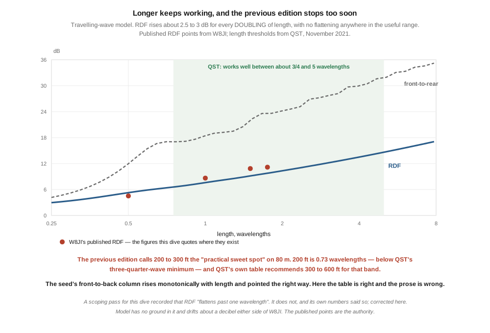
And the length recommendation stops below the published minimum. §3.3 calls 200 to 300 feet “the practical sweet spot” on 80 metres. Two hundred feet is 0.73 wavelengths there, and the standard reference puts the minimum at three-quarters of a wavelength and the recommended range at 300 to 600 feet. §4 works out what the extra wire is worth — about two and a half to three decibels of RDF for every doubling, all the way out to the five-wavelength ceiling the chapter never mentions.
⭐⭐ One thing in the chapter pointed the right way and was overruled by its own prose. The fractional-length table in §3.3 shows front-to-back ratio climbing steadily with length, right out to 3.75 wavelengths. That column is correct in its trend, and it argues for building longer. The paragraph underneath it recommends the shortest entries. This dive has repeatedly found drawings contradicting prose; here it is a table contradicting prose, and the table is the one to believe.
⚠ A correction to this dive’s own working notes. The scoping pass for this volume recorded that RDF “rises steeply to about one wavelength and then flattens”, and concluded on that basis that the chapter’s sweet spot was right. It does not flatten — the scoping run’s own numbers show a steady rise — and the conclusion drawn from it was wrong. §4 gives the corrected picture. The lesson is the one this program keeps relearning: audit before asserting a trend, including your own.
2.2 The polarisation, and the sentence that inverts it
A beverage is a long horizontal wire a few feet above the ground, and the chapter reasons from its shape to its polarisation: the wire is horizontal, therefore the antenna is horizontally polarised. That is the wrong inference, and it matters more here than it would almost anywhere else, because polarisation is the operating principle of this antenna.
The standard reference is unambiguous. Ward Silver N0AX and Frank Donovan W3LPL, writing the centenary account in QST:
That means the Beverage antenna is most sensitive to vertically polarized signals arriving in line with the antenna.
Vertically polarised. The horizontal wire responds to a vertically polarised wave, and the way it does so is the thing the chapter never explains.
2.2.1 Wave tilt
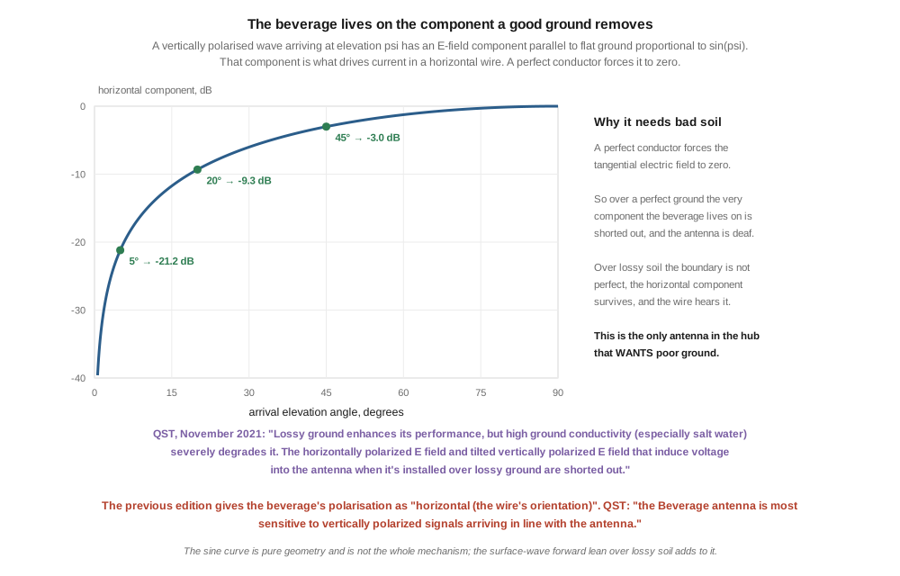
A wave’s electric field is perpendicular to its direction of travel. A vertically polarised wave arriving from directly overhead therefore has its E field lying flat, parallel to the ground; a vertically polarised wave arriving along the horizon has its E field standing straight up. In between, at elevation angle ψ, the component parallel to flat ground is proportional to sin ψ.
That horizontal component is what drives current in a horizontal wire. It is pure geometry, and it exists before any ground effect is considered at all:
Table 1 — That horizontal component is what drives current in a horizontal wire. It is pure geometry, and it exists before any ground effect is considered at all
| arrival elevation | horizontal fraction | relative to 90° |
|---|---|---|
| 1° | 0.0175 | −35.2 dB |
| 5° | 0.0872 | −21.2 dB |
| 10° | 0.174 | −15.2 dB |
| 20° | 0.342 | −9.3 dB |
| 45° | 0.707 | −3.0 dB |
⚠ That is not the whole mechanism and must not be presented as if it were. The literature carries two accounts of wave tilt and they are not the same. QST attributes it to the arrival geometry and the ground together — “Incoming signal wave fronts tilt at ground level, due to reflection in the ionosphere and the effects of ground” — while the classic surface-wave treatment describes a vertically polarised wave travelling over finite-conductivity soil as leaning forward, because part of the wavefront is in air and part is in dirt with a slower velocity, and a wavefront cannot be discontinuous.
⭐ Both produce a horizontal E-field component along the wire, and the antenna does not care which one it is getting. The honest statement is that the component exists, that it is small, and that the beverage is built to integrate a small component over a long distance rather than to capture a large one at a point.
⭐⭐ And the table above explains the elevation pattern for free. The horizontal component vanishes at zero elevation and grows with arrival angle — but the ground attenuates a horizontal field close to it, and increasingly so as it lies flatter. QST again: “When sky-wave signals arrive from nearly overhead, both horizontally and vertically polarized E fields are parallel to Earth. They are severely attenuated when close to Earth, before inducing a voltage into the antenna.” The two effects pull in opposite directions and leave a response that favours low angles, which is exactly what a low-band DX antenna wants and is why the beverage has survived a hundred years without modification.
2.3 Why it wants bad ground
The chapter mentions ground twice, both times in passing. It is the whole story.
Take the boundary condition at a perfect conductor: the tangential electric field is zero. It has to be — a perfect conductor cannot sustain a field along its surface, because any such field would drive infinite current. So a horizontal wire sitting just above a perfect ground plane sees no horizontal E field at all, whatever is arriving from the sky.
That is the field the beverage lives on. Remove it and the antenna is deaf.
QST states the consequence directly, and it is worth quoting in full because it is the sentence the chapter needed:
Ground conductivity has a big effect on Beverage performance. Lossy ground enhances its performance, but high ground conductivity (especially salt water) severely degrades it. The horizontally polarized E field and tilted vertically polarized E field that induce voltage into the antenna when it’s installed over lossy ground are shorted out. Unlike transmitting antennas, the Beverage requires medium or poor ground conductivity to work well.
⭐⭐⭐ This is the only antenna in this hub that is made worse by improving its ground. Every vertical in the fixed vertical monopoles dive wants the best ground system its owner can afford; the whole radial-field literature exists to reduce ground loss. A beverage wants the opposite. Salt water, the ideal ground for a vertical, is close to the worst possible ground for a beverage.
⚠ This has a practical consequence the chapter should have drawn. A beverage that works beautifully at one station may disappoint at another for no reason connected to how it was built. Soil conductivity is a property of the site, not of the antenna, and it is not something the builder controls. Before blaming the construction, find out what the ground is.
⭐ It also resolves an apparent paradox in the chapter’s own framing. It calls the beverage “lossy” and treats that as a cost to be tolerated. Vol 1 showed loss is free on receive — and here the loss is not merely tolerable, it is the mechanism. The energy the ground absorbs is what makes the antenna directional in the first place.
2.4 How long, and the recommendation that stops short
The chapter offers a table of fractional-wavelength beverages and a verdict:
For 80 m, 200–300 ft of beverage is the practical sweet spot.
At 3.6 MHz a wavelength is 83.3 m, or 273 feet. So:
Table 2 — At 3.6 MHz a wavelength is 83.3 m, or 273 feet. So
| length | wavelengths on 80 m | RDF | verdict |
|---|---|---|---|
| 200 ft | 0.73 | 6.50 | below the published ¾ λ minimum |
| 300 ft | 1.10 | 7.96 | in the good-performance band |
| 400 ft | 1.46 | 9.04 | in the good-performance band |
| 500 ft | 1.83 | 9.95 | in the good-performance band |
| 600 ft | 2.20 | 10.73 | still improving |
| 900 ft | 3.29 | 12.56 | still improving |
Against the published guidance:
Beverages work well over a fairly wide frequency range where they’re between about ¾ and 5 λ long, with good performance around 1 to 2 λ.
and QST’s Table 1, Recommended Beverage Lengths: 160 m, 500–1,200 ft · 80 m, 300–600 ft · 40 m, 200–500 ft.
🔴 The chapter’s sweet spot begins below the published minimum and ends at the published minimum. Two hundred feet on 80 metres is not a sweet spot; it is slightly less antenna than the standard reference considers usable. Three hundred feet — the top of the chapter’s range — is the bottom of QST’s.
2.4.1 What the extra wire buys
RDF does not level off anywhere in the usable range. It climbs by roughly 2.5 to 3 decibels for every doubling of length:
Table 3 — RDF does not level off anywhere in the usable range. It climbs by roughly 2.5 to 3 decibels for every doubling of length
| length | RDF | change per doubling |
|---|---|---|
| 0.25 λ | 2.97 | |
| 0.5 λ | 5.28 | +2.31 |
| 1 λ | 7.60 | +2.47 |
| 2 λ | 10.33 | +2.85 |
| 4 λ | 13.50 | +3.31 |
| 5 λ | 14.63 | +3.50 |
⚠ This is where the correction to my own scoping note belongs. That pass recorded RDF as “rising steeply to about 1 λ and then flattening”, and used it to endorse the chapter’s short recommendation. The numbers above were in that same run and show no flattening. What is true is that returns diminish per foot of wire — doubling the length costs twice the copper and twice the real estate for a fixed 2.5 to 3 dB — but that is a different statement, and it argues for going as long as the land allows rather than for stopping.
⭐ W8JI’s published RDF figures agree with the shape: 4.52 dB at ½ λ, 8.64 at 1 λ, 10.84 at 1½ λ, 11.16 at 1¾ λ. ⚠ That last step looks like flattening and is not — 1.5 λ to 1.75 λ is a seventeen per cent increase in length, not a doubling. Read the axis before reading the trend.
⚠ And the model behind the table above has no ground in it, which for this antenna is a serious omission. It sits about a decibel either side of W8JI’s published values across the useful range. Where a published figure exists, quote the published figure; the computation is here to establish the shape of the curve and to test the chapter’s reasoning, not to replace a NEC model run over defined soil.
2.4.2 The ceiling the chapter never mentions
The chapter’s table runs to 3.75 λ with front-to-back still climbing and no upper limit stated, which invites the reader to conclude that longer is always better. It is not:
With a length above 5 λ, sensitivity begins to decline because voltages and currents induced by the tilted wave front start interfering with voltages and currents traveling along the antenna to the feed point.
⭐ That is a real limit with a physical mechanism — the wave and the wire current travel at slightly different speeds, so beyond a certain length they fall out of step and the later contributions start subtracting. The velocity factor of the wire is what sets it, which is why the model in this volume carries one.
2.5 One wire, three bands
The chapter treats length as a per-band decision, tabulating fractional wavelengths on 80 metres and discussing 160-metre beverages separately. It never says that the same wire serves several bands, and that it gets better as frequency rises.
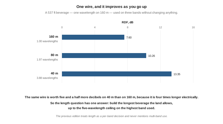
Consider that a Beverage antenna that’s 1 λ long at 160 meters will be 2 λ on 80 meters and 4 λ on 40 meters. The antenna can be used on all of these frequencies.
Worked through, for a 537-foot wire — one wavelength at 1.83 MHz:
Table 4 — Worked through, for a 537-foot wire — one wavelength at 1.83 MHz
| band | electrical length | RDF | beamwidth |
|---|---|---|---|
| 160 m | 1.00 λ | 7.60 dB | 108° |
| 80 m | 1.97 λ | 10.26 dB | 73° |
| 40 m | 3.88 λ | 13.35 dB | 48° |
⭐⭐ The same piece of wire is worth five and a half more decibels on 40 metres than on 160, purely because it is four times longer electrically. Nothing is switched, tuned or changed.
⭐ So the length question has a single answer, and it is simpler than the chapter’s per-band tables suggest: build the longest beverage the land allows, up to the five-wavelength ceiling on the highest band you intend to use it on. A 537-foot wire is already 3.9 λ on 40 metres and would be 7.6 λ on 20 — past the ceiling, and 20 metres is not a band where anyone needs a beverage anyway.
⚠ The beamwidth column is the cost. At 48° on 40 metres the antenna has become genuinely directional, and a station off the beam is a station you will not hear. This is the real argument for the switched multi-beverage installations the chapter describes — not that each needs a different length, but that a long beverage on a high band is narrow.
2.6 Front-to-back, and why it is not a design quantity here
Vol 1 established that front-to-back ratio is the wrong figure of merit for a receiving antenna. The beverage supplies an unusually clean demonstration of why, and it comes out of the same travelling-wave model.
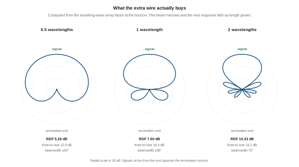
The rear response of a travelling-wave wire is a sinc function, and a sinc has zeros. As the length is tuned, those zeros sweep across the rear bearing. Sampled at exactly 180°, the computed front-to-back ratio swings between a few decibels and — at the lengths where a null lands on that bearing — an arbitrarily large number limited only by how finely the model is sampled.
Meanwhile, the same patterns measured properly rise smoothly:
Table 5 — Meanwhile, the same patterns measured properly rise smoothly
| length | RDF | front-to-rear | point front-to-back |
|---|---|---|---|
| 0.25 λ | 2.97 | 4.17 | 4.1 |
| 0.5 λ | 5.28 | 11.97 | very large |
| 0.75 λ | 6.57 | 17.05 | 13.6 |
| 1 λ | 7.60 | 18.44 | very large |
| 2 λ | 10.33 | 24.22 | very large |
| 4 λ | 13.50 | 30.02 | very large |
where front-to-rear compares the peak against the average of the whole rear hemisphere rather than against one bearing.
⭐⭐ A single-bearing number that leaps between 4 dB and infinity as you let out ten more feet of wire is not a design quantity. In a real installation the null is filled in by termination error, ground loss and reflections from everything in the field, so nobody ever measures infinity — which is another way of saying that the published front-to-back figure for a beverage is set by the quality of the installation rather than by the design. RDF and front-to-rear are properties of the antenna.
⚠ Two things follow, and the second is a defence of the chapter. First, do not choose a beverage length to maximise front-to-back; the maximum is a knife edge you cannot hold. Second — the chapter’s own front-to-back column behaves much more like a front-to-rear figure than like a point measurement, rising smoothly from 12–15 dB to 28–32 dB across its five rows. Compared against the front-to-rear column above it is optimistic at the short end and close at the long end. It is a reasonable engineering table wearing the wrong label, which is a much smaller criticism than it first appears.
2.7 The gain figure nobody can compare
§3.2 gives the beverage’s forward gain as “−5 to −15 dBi (yes, negative — beverages are lossy)”. QST’s modelled pattern for a 2 λ 160-metre beverage is annotated “Max Gain = 8.52 dBi, Freq = 1.83 MHz, Elevation Angle = 10°”.
Those two figures differ by about twenty decibels, and both are described as gain in dBi for a beverage.
🔴 They cannot both be the same quantity, and neither states enough to say which. The variables that would settle it:
- the elevation angle, which QST gives as 10° and the chapter does not give at all;
- whether ground loss is included, or whether the figure is pattern directivity only;
- the ground constants assumed, which for this antenna change the answer more than for any other;
- the length, which the chapter’s figure does not attach to.
⚠⚠ Do not pick one. This is the shape the antenna tuners dive named: a number that is under-specified rather than wrong. Both figures are probably defensible under their own unstated assumptions, and settling it needs a NEC model over defined soil, which this dive cannot run. ▶ Recorded as owed work.
⭐ And it matters less than it looks. Vol 1 established that absolute gain is not the figure of merit for a receiving antenna — it cancels out of the signal-to-noise ratio when external noise dominates. A beverage’s gain figure tells you how much preamplification you will need to keep the signal above the receiver’s own noise, and nothing about how well it hears. The chapter’s instinct in flagging the negative number and then dismissing it is right; only the number is unmoored.
2.8 What the previous edition gets right
Over-correction is a named failure mode in this program, and this chapter’s practical content is largely sound. Checked against QST:
Table 6 — Over-correction is a named failure mode in this program, and this chapter's practical content is largely sound. Checked against QST
| the chapter | the reference |
|---|---|
| termination ~470 Ω | ”Most Beverages have a characteristic impedance of about 500 Ω. The exact value is relatively unimportant to the performance of the antenna.” |
| fed through a 9:1 unun to 50 Ω | QST Figure 1: “a 9:1 impedance transformer provides a good match to 50 Ω coaxial cable”, drawn as a 1:3 turns ratio |
| height 1.5–3 m | ”Typical heights range about 6 – 10 feet.” |
| non-resonant, wide bandwidth | ”it never has standing waves from reflections from the ends of the wire. As a result, it’s also non-resonant” |
| the termination makes it unidirectional | ”could be made unidirectional by keeping it close to the ground and terminating one end of the wire with a resistor” |
⚠ Do not “correct” 470 Ω to 500 Ω. The reference that supplies the 500 Ω figure says in the same breath that the exact value barely matters, and 470 Ω is a standard resistor value. The chapter chose a real part; that is better engineering than quoting a round number.
⭐ The multi-beverage switched installation the chapter describes is also right, and §5’s beamwidth column is the reason: a long beverage on a high band is narrow, so covering several directions needs several wires and a switch rather than one wire and a rotator.
2.8.1 Two things to sharpen
⚠ The date is a patent date, not a development date. The chapter says the antenna was developed by “Harold Beverage and partners (RCA, 1921)”. QST: “On June 7, 1921, Harold Beverage, W2BML, (previously 2BML) obtained his first patent for his radio receiving system.” The canonical technical paper is Beverage, Rice and Kellogg, The Wave Antenna: A New Type of Highly Directive Antenna, AIEE 1923 — which is where the “partners” belong and where the theory was published.
⚠ The inclined-wire claim is unsupported. §3.1 says “The wire is not horizontal — it’s slightly inclined upward (toward the feedpoint) or downward (toward the termination). This is a subtle but real design choice that affects the pattern.” Nothing in the reference supports it, and QST says the opposite about sensitivity to height: “The antenna isn’t particularly sensitive to small variations in height above ground … unless the variations exceed about 0.1 λ, which is about 50 feet at 160 meters, they’ll have little effect.” A deliberate slope of less than fifty feet at 160 metres is, by that standard, not a design parameter. ▶ Flagged rather than deleted; it may be a real technique from a source the chapter does not cite, and a fifty-foot criterion is not the same as proof that a slope does nothing.
2.9 Where this volume hands off
The beverage is a hundred-year-old antenna that has not needed changing, and the chapter’s affection for it is warranted. What the chapter gets wrong is what it is listening to. A beverage receives vertically polarised signals through the small horizontal field component that wave tilt provides, and the chapter’s “horizontal (the wire’s orientation)” reads the polarisation off the shape. The requirement that follows is the one that most surprises a reader coming from transmitting antennas: this antenna needs poor soil, because a good conductor shorts out the very field it lives on.
On length, the chapter’s recommendation begins below the published minimum and its own table pointed the right way. RDF rises 2.5 to 3 decibels per doubling with no flattening, out to a five-wavelength ceiling the chapter never mentions — and one long wire serves 160, 80 and 40 metres, improving as it goes.
From here:
- Vol 3 takes the small terminated loops, which exist because most people cannot fit any of the lengths in §4 and which trade a few decibels of RDF for a thirty-foot footprint.
- Vol 4 takes active loops and ferrite rods, where the amplifier’s noise figure re-enters the argument.
- Vol 5 builds and measures, and owes this volume a soil-conductivity measurement.
- Fixed vertical monopoles, Vol 1 is the antenna that wants the ground a beverage does not.
- Baluns and ununs, Vol 4 is the 9:1 transformer at the feed point.
- Vol 1 is where RDF and the two noise cases come from.
Three things are owed. A NEC model over defined ground, which would settle §7’s gain question and replace §4’s ground-free curve with a real one. A soil-conductivity figure for the site, since §3 makes it the dominant variable and no builder measures it. And an independent accuracy review, which no volume in this dive has had.
2.10 Resources
- Ward Silver, N0AX, and Frank Donovan, W3LPL, “The Beverage Antenna, 100 Years Later”, QST, November 2021, pp. 55–57 — the polarisation statement, the shorting mechanism, the recommended lengths, the characteristic impedance, the height range and the five-wavelength ceiling. Every quotation in this volume is from this article unless stated otherwise.
- H. H. Beverage, C. W. Rice and E. W. Kellogg, The Wave Antenna: A New Type of Highly Directive Antenna, AIEE Transactions, 1923 — the original theory. ⚠ Cited here from secondary accounts; not read directly.
- W8JI, Comparison of Beverage antenna, magnetic loop antenna, and phased vertical receiving antennas — the published RDF figures §4 checks against, and the beverage-construction notes QST recommends.
- ON4UN, Low-Band DXing — the standard practical treatment, and the source QST refers readers to for two-wire and switched installations.
- Recommendation ITU-R P.372-13, Radio noise — the noise regime Vol 1 rebuilt.
- Vol 1 — RDF against front-to-back, and the distinction between localised and distributed noise.
- Fixed vertical monopoles, Vol 1 — the ground system a beverage does not want.
- Baluns and ununs, Vol 4 — the 9:1 unun and its winding.
- Antenna tuners, Vol 3 — the under-specified-number failure §7 recognises.
Comments (0)