Single-Band Dipoles · Volume 4
Variants — Folded, Inverted-V, Sloper, and Vertical Dipole
Bending the canonical half-wave reference into deployable shapes: the folded dipole's 4× impedance step-up and wideband bonus, the inverted-V's single-mast convenience and apex-angle trade, the sloper's directivity toward the low end (and its half-sloper cousin), and the vertical dipole's omnidirectional, radial-free DX case
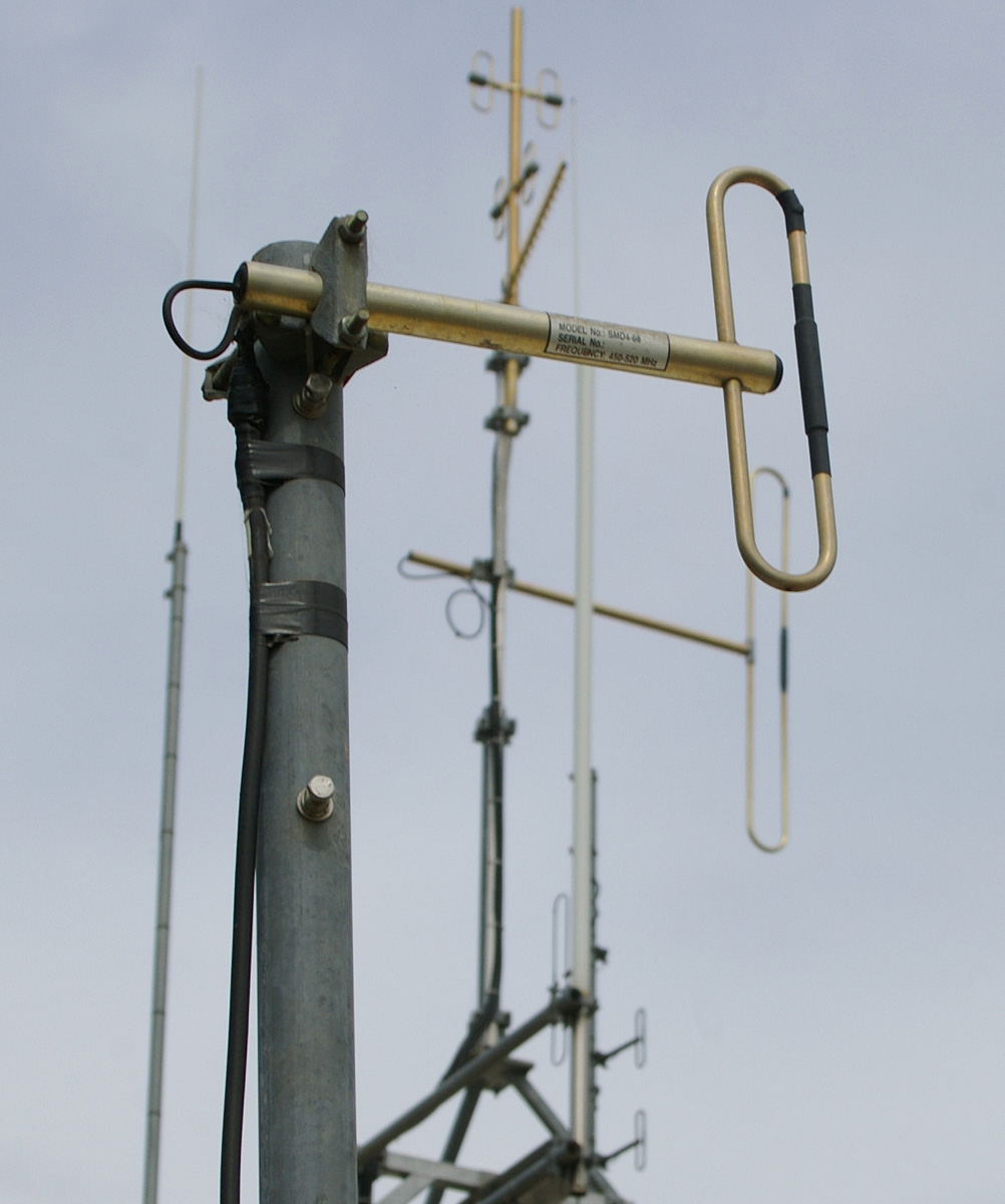
4.1 About this volume
Vol 1 fixed the geometry and physics of the canonical straight, center-fed, horizontal half-wave element. Vol 2 took ownership of its feedpoint — the free-space 73 + j42.5 Ω, the height-dependent resistance over real ground, and the 1:1 current balun that belongs at every dipole feed. Vol 3 developed the radiation pattern and the SWR-versus-frequency behavior in full — the free-space donut and figure-8, the ground-reflection lobing, the takeoff-angle-versus-height curve, NVIS, and the element-Q-set bandwidth. Every one of those volumes treated the dipole as a straight, horizontal, two-equal-legs structure, because that is the configuration the underlying theory is cleanest to derive for.
Almost nobody’s actual installation is that clean. A single mast is available, not two; the feedpoint impedance a particular site needs is not 73 Ω; a tower is already up and standing idle; the operating goal is DX from a small lot with no room for a sprawling horizontal wire. This volume covers the four mechanical and topological variants that answer those real constraints while staying inside the single-band, half-wave-family box — the folded dipole (two parallel conductors, shorted at the ends, stepping the feedpoint impedance up 4×), the inverted-V (the same element drooped from one central support, trading gain and pattern purity for a single mast), the sloper and its cousin the half-sloper (the element run at a slope off a tower, trading symmetry for directivity toward the low end), and the vertical dipole or “flagpole” (the element stood on end, trading the horizontal figure-8 for omnidirectional azimuth and a naturally low takeoff angle with no ground or radial system at all).
Each variant is still, electrically, the half-wave dipole of Vol 1 — the same cos(βz) current distribution, the same order-of-magnitude radiation resistance, the same 468/f starting length. What changes, variant by variant, is the feedpoint impedance, the radiation pattern, and the mechanical problem being solved. This volume works through each in turn, with a hand-authored geometry figure for every variant, verified feedpoint-impedance figures where the literature gives them cleanly (the folded dipole’s 4× step-up and the inverted-V’s apex-angle-versus-Z relationship both check out against the ARRL Antenna Book and Balanis), and a brief buy-side note pointing at a real, currently available product in each case — the full commercial-buy survey is Vol 5’s job, not this one’s. The comparative pattern figure in Section 6 puts all four variants’ azimuth and elevation shapes side by side against the Vol 1–Vol 3 reference so the differences are visible at a glance rather than only described in prose.
4.2 Folded dipole — the 4× impedance step-up
4.2.1 Geometry
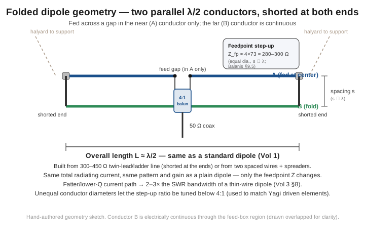
A folded dipole is two parallel conductors, each a half-wavelength long, shorted together at both ends, with the feed inserted as a gap at the center of only one of the two conductors. Picture a standard dipole and a second, unbroken wire run alongside it at a small spacing s (small compared to a wavelength), with the two wires strapped together at each tip. The fed conductor sees a break at its center where the coax (through a balun) attaches; the second conductor is continuous straight through. Mechanically the whole assembly is most often built as a single run of 300 Ω twin-lead or 450 Ω ladder line with the two conductors shorted together at each end and split at the center for the feed, or, at HF power levels where twin-lead’s voltage rating is a concern, as two separate wires held at constant spacing by insulating spreaders every 30 cm or so.
4.2.2 Feedpoint impedance — the 4× step-up, derived
The headline number is that a folded dipole’s feedpoint impedance is close to 4× the impedance of an equivalent single-wire dipole — roughly 4 × 73 ≈ 280–300 Ω in free space, the widely quoted round number that also happens to match 300 Ω twin-lead almost exactly (which is no coincidence; twin-lead’s own characteristic impedance was chosen with this application in mind). The factor of 4 is not an empirical rule of thumb; it falls out of a clean piece of transmission-line-transformer theory that Balanis develops as the transmission-line-mode / antenna-mode superposition (Balanis, Antenna Theory, §9.5). The two-conductor structure supports two independent current modes simultaneously. The antenna mode is the symmetric mode — equal currents in phase on both conductors — which is what actually radiates and looks, from the far field, exactly like a single dipole carrying the sum of the two conductors’ currents. The transmission-line mode is the differential mode — equal and opposite currents circulating around the two-wire loop formed by the parallel conductors and their shorted ends — which does not radiate (the fields from the closely spaced, oppositely directed currents cancel) but does load the feedpoint, behaving exactly like a shorted quarter-wavelength transmission-line stub, which presents a very high impedance at resonance.
Working through the boundary conditions for two identical, closely spaced conductors (s ≪ λ), the transmission-line mode’s high stub impedance appears in parallel with the antenna-mode impedance in such a way that essentially all of the antenna mode’s current is forced to split evenly between the two conductors, while all of the drive voltage appears across only the fed conductor’s gap. The upshot, worked all the way through, is a strikingly clean result:
Z_fp(folded) ≈ 4 × Z_fp(single dipole),
for equal-diameter conductors at close spacing. With the Vol 2 73 + j42.5 Ω free-space single-dipole figure as the baseline, this gives Z_fp(folded) ≈ 292 + j170 Ω before trimming, and — once trimmed to resonance exactly as the single dipole is — a resonant free-space feedpoint in the neighborhood of 280–300 Ω, purely resistive. This is a well-established figure in the antenna literature (it is standard material in both the ARRL Antenna Book and Balanis), and the “300 Ω” round number is common enough that it has become synonymous with “folded dipole” the way “73 Ω” is synonymous with “dipole.” A useful additional fact, less often exploited by hobbyists than by antenna designers: because the 4:1 ratio is a limiting case for equal-diameter, closely-spaced conductors, making the two conductors different diameters lets the step-up ratio be tuned continuously to values other than 4 — the technique used to synthesize a Yagi driven element’s folded-dipole impedance match to a specific target (commonly in the 2–3× range) rather than accepting a flat 4×.
4.2.3 Matching — the 4:1 balun
A feedpoint in the 280–300 Ω range wants a 4:1 balun to bring it down to 50–75 Ω coax, exactly as a plain dipole’s ~73 Ω wants the 1:1 current balun of Vol 2. The transformation itself is a straightforward impedance ratio; what still has to be respected is Vol 2’s balance argument — a folded dipole is every bit as balanced a load as a plain dipole, and an unbalanced coax feed invites the same common-mode current problem if the balun is only a voltage transformer rather than a proper current-type 4:1 Guanella. The historical alternative — feeding the antenna directly with 300 Ω twin-lead all the way back to a balanced antenna tuner, no balun at all — sidesteps the transformation entirely and was the standard practice for decades of FM and TV reception before 75 Ω coax became universal; it remains a legitimate option where a balanced tuner is already on the bench.
4.2.4 Why it’s used: bandwidth, robustness, and the twin-lead legacy
The impedance step-up is the number everyone quotes, but the more operationally useful property is what the two-conductor geometry does to bandwidth. Vol 3 §8 established that a dipole’s 2:1-SWR bandwidth is set by the element’s Q, and Q falls as the effective conductor gets electrically fatter. A folded dipole’s parallel-conductor current path is, in exactly this sense, a fatter effective radiator than a single wire of the same gauge — the current is smoothed and spread across two conductors rather than concentrated in one — and the practical result is 2–3× the SWR bandwidth of an equivalent thin-wire dipole, with essentially no gain penalty (the pattern is unchanged from a plain dipole, because the antenna mode is what radiates and it looks identical to a single dipole carrying the same total current). This bandwidth bonus, not the impedance figure, is the real reason to reach for a folded dipole on 80 m, where Vol 3’s table showed a thin-wire dipole covering barely a third of the band at 2:1 SWR: a folded 80 m dipole can cover CW and phone without retuning, at the cost of the extra conductor and the 4:1 balun.
The other reason the folded dipole is ubiquitous has nothing to do with amateur HF at all. Every FM and VHF-TV twin-lead antenna ever bundled with a home stereo receiver is, electrically, a folded dipole built directly from 300 Ω ribbon cable — the cheap, ubiquitous “T-shaped” antenna that ships in the box with practically every FM tuner is exactly the geometry of Section 2’s figure, sized for the FM band. Mechanical robustness is the other half of the story: twin-lead or ladder-line construction, or two wires on rigid spreaders, is a physically stronger structure than a single thin wire, and the wider bandwidth means less sensitivity to the small detuning that ice, wind-induced stretch, or a slightly-off trim introduce — a genuine advantage for a semi-permanent or unattended installation.
Buy note. At the consumer end, the classic 300 Ω twin-lead folded dipole survives essentially unchanged as the antenna bundled with, or sold as an accessory to, home FM tuners and receivers — the Bingfu 300 Ω FM dipole antenna (a few dollars, budget tier, sold on Amazon and similar outlets) is a current, easily verified example of exactly this geometry, still built from bare 300 Ω twin-lead with spade or bare-wire terminals. At the professional end, broadcast-grade FM and TV panel antennas from manufacturers such as Shively, ERI, and Dielectric commonly use folded-dipole radiating elements for the same bandwidth reason, at a price tier that has nothing to do with amateur budgets. In between, dedicated amateur “buy a folded dipole” products are uncommon — the antenna is cheap and simple enough that it is almost always homebrew, or purchased as a 4:1 balun + wire/ladder-line kit rather than a complete turnkey antenna; the deep buy-side survey for baluns and wire kits is Vol 5’s subject.
4.3 Inverted-V — single-mast convenience and the apex-angle trade
4.3.1 Geometry
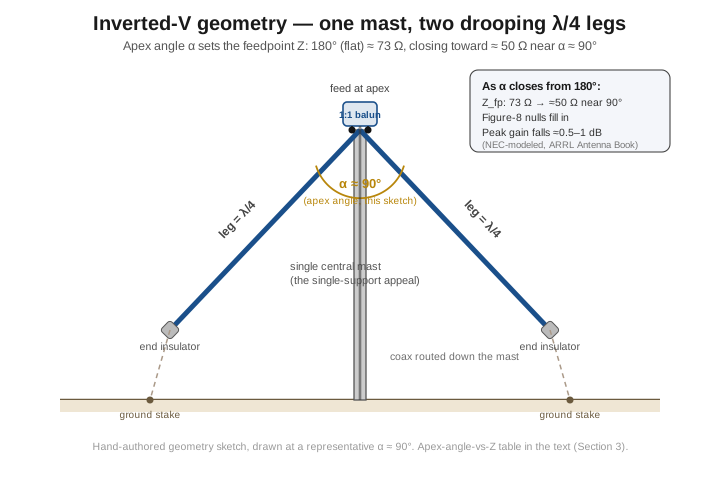
An inverted-V is the same half-wave dipole of Vol 1, fed at the same center point, but with both legs drooping down and away from a single central support instead of running flat between two supports. The apex — the feedpoint — sits at the top of one mast; each leg runs down at an angle to its own end insulator and ground anchor, tensioned by a guy rope rather than a second mast. The angle between the two legs at the apex, the apex angle α, is the single geometric parameter that governs everything else about the antenna’s electrical behavior, and it is the parameter a builder controls directly by choosing how high the mast is relative to how far out the end anchors are staked.
4.3.2 The apex-angle effect on impedance, pattern, and gain
Closing the apex angle from the flat dipole’s α = 180° moves three things simultaneously, and the direction of all three is the same: toward a more compact, more forgiving, slightly less capable antenna. Feedpoint resistance falls. At α = 180° (the flat reference) the feedpoint sits at the free-space 73 Ω of Vol 1/Vol 2. As the legs droop, mutual coupling between the two halves of the now-nonlinear element changes, and the resistance drops steadily — representative NEC-modeled figures reproduced in the ARRL Antenna Book and widely corroborated in the amateur literature put it at roughly 65 Ω near α = 120° and 50 Ω near α = 90°, which is the reason α ≈ 90° earned the label “the standard inverted-V”: it is close to the one apex angle that presents a natural, transformer-free match to 50 Ω coax. The figure-8 pattern fills in. Vol 3 developed the flat dipole’s deep, narrow end-nulls as a consequence of the antenna’s straight-line current distribution; bending the element breaks that clean geometry, and the once-sharp nulls soften and partially fill, trading a small amount of directivity for a broader, more nearly omnidirectional coverage. Peak gain falls slightly — on the order of half a dB to a dB relative to the flat dipole at the same average height, a real but modest cost.
Table 1 — The apex-angle effect on impedance, pattern, and gain
Apex angle α | Each leg droop from horizontal | Feedpoint Z (representative) | Pattern | Notes |
|---|---|---|---|---|
| 180° (flat dipole) | 0° | ≈ 73 Ω | Sharp figure-8, deep nulls | The Vol 1–Vol 3 reference |
| 120° (mild V) | 30° | ≈ 65 Ω | Softened figure-8 | A common compromise where mast height allows it |
| 90° (standard V) | 45° | ≈ 50 Ω | Filled, more nearly omnidirectional | The conventional “inverted-V,” natural 50 Ω match |
| 60° (steep V) | 60° | ≈ 40 Ω | Nearly omnidirectional | Used mainly where mast height forces a steep droop |
These figures are NEC-model-derived and reproduced across the amateur literature rather than a closed-form textbook result the way the folded dipole’s 4× is; treat the specific ohm values as representative of a well-built installation rather than a guaranteed number for any given mast height, wire gauge, and ground — a NanoVNA sweep after hoisting (Vol 5) is what actually tells you where your particular inverted-V landed. What is dependable is the direction of every trend in the table: closing the angle always drops R, always fills the nulls, and always costs a little gain, and the practical design freedom this hands the builder is real — an inverted-V’s apex angle can be chosen, within the limits of the available mast height and lot size, to land the feedpoint resistance close to 50 Ω without any matching network at all.
4.3.3 Why it’s what most amateurs actually build
The apex-angle costs are real but modest, and they buy something operationally decisive: only one support is required. A flat dipole needs two masts, two trees, or a mast and a tall structure at both ends of the wire, spaced the antenna’s full physical length apart — for an 80 m dipole, on the order of 40 m between supports, a footprint few residential lots have. An inverted-V needs exactly one elevated point, with both ends anchored down near ground level at whatever spacing the lot allows; the legs can be brought in steeper (a smaller apex angle) if the lot is tight, at the cost described above. This is why, when an amateur says “I put up a dipole,” the antenna on the far end of the coax is, more often than not, actually an inverted-V — the single-mast convenience is decisive for anyone without two tall, conveniently-spaced supports, and the pattern-broadening is frequently a feature rather than a bug for general-purpose HF operation, since a slightly-filled-in figure-8 is more forgiving of an imperfect orientation toward the stations you actually want to work.
Buy note. Because an inverted-V is electrically identical to a plain dipole with drooped legs, the commercial “buy” side is the same wire-and-hardware kit that serves a flat dipole — a pair of end insulators, a center insulator/balun assembly, and precut or spooled wire. DX Engineering’s single-band dipole kits span two tiers: the DXE-DWK family is a low-cost hardware-only kit (insulators and hardware, no wire or balun — well under $100), while the DXE-RDPK is a premium legal-limit complete kit (around $235 per band) that already bundles precut 14 AWG wire, a center bracket, end insulators, and its own DXE-MC20-1-1 Maxi-Core 1:1 balun. Nothing about either changes for inverted-V use beyond how you stake the ends — the deep survey of these kits and their balun pairings is Vol 5’s job.
4.4 Sloper and half-sloper — trading symmetry for directivity
4.4.1 Geometry: full sloper vs. half-sloper
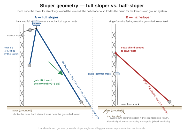
A sloper takes the half-wave element and tilts the whole thing off horizontal, feeding it near the top of a tall support — almost always an existing tower — with the wire running down and away at a slope rather than horizontally or symmetrically drooped. Two genuinely different antennas share the name, and conflating them is a common source of confusion in the amateur literature, so it is worth being precise. The full sloper (sometimes called the sloping dipole) is a true balanced two-wire half-wave dipole, fed through a 1:1 current balun exactly as a flat dipole or inverted-V would be, with the tower serving purely as a mechanical attachment point via an insulated standoff bracket — the tower carries no antenna current by design, though in practice a leg run close alongside a grounded tower does couple to it, which is why aggressive common-mode choking of the feedline is standard practice for any sloper mounted near steel. The half-sloper is a different and simpler animal electrically: a single wire, roughly a quarter-wavelength long, fed between the tower structure itself and a point partway up it, with the tower’s own grounded mass and guy-wire system serving as the counterpoise — this configuration is documented in the literature as the “quarter-wave sloper with counterpoise” (QWSWC), and it behaves electrically much closer to a bent, sloping quarter-wave monopole (the subject of the hub’s Fixed Verticals dive) than to a genuine dipole, because one side of its feed is the tower’s ground system rather than a second matched radiating arm.
4.4.2 Directivity toward the low end
The property that makes a sloper worth building, in either form, is that it is not bidirectional the way a flat dipole or inverted-V is. Tilting the element breaks the front-back symmetry that a horizontal dipole’s broadside figure-8 depends on, and the practical result — documented consistently across the amateur antenna literature, though the exact figure is installation-dependent rather than a clean closed-form number — is a gain lift on the order of 2–3 dB toward the low (downslope) end of the antenna relative to the high end, with a corresponding reduction looking back toward the tower. A sloper is, in other words, a cheap way to get a favored direction out of a single tall support without building a rotatable Yagi: point the low end toward a favored DX path, or away from a known local noise source, and the antenna does the rest. The slope also introduces a genuine vertical-polarization component into the radiation (a pure horizontal dipole radiates none), which on some paths — particularly low-angle DX work where ground-reflection geometry favors vertical polarization — is a further, if secondary, advantage.
4.4.3 Ground-plane and tower dependence, and feed practice
Both sloper variants are more sensitive to their supporting structure than a free-standing dipole or inverted-V, just in different ways. The full sloper’s near-tower leg genuinely does couple to a grounded tower at close spacing even though the two are not bonded, which detunes the antenna somewhat from its free-standing NEC prediction and — more importantly for RFI hygiene — makes an unchoked feedline near the tower a strong invitation to the common-mode problem Vol 2 developed; a feedpoint choke chosen for the aggressive end of the Vol 2 Z_cm range, plus care in routing the coax away from the tower where practical, is the standard cure. The half-sloper is dependent on the tower’s ground system by design — the antenna simply does not work as intended without a solidly grounded tower and an adequate base ground/guy-wire counterpoise, since that system is electrically one whole side of the antenna, not an afterthought. Both variants share a mechanical feed-line rule worth carrying from the general sloper literature: routing at least a quarter-wavelength of the feedline at roughly 90° to the sloping element, before it is allowed to run parallel to the wire, measurably reduces feedline coupling into the antenna and is cheap insurance to build in from the start.
4.4.4 Where it wins, and its modern niche
A sloper’s case is narrowest of the four variants in this volume: it earns its keep specifically where a tall tower is already standing (most often a tower built for VHF/UHF beams or a rotatable HF Yagi) and the operator wants a single-band, low-cost, favored-direction HF antenna riding along on that same structure with minimal additional real estate — a mast that would otherwise stand there unused becomes a directional low-band antenna for the cost of some wire, a balun, and insulators. It is a poor fit for anyone without a tall support already in place, since building a tower for the sole purpose of a wire sloper is rarely the most cost-effective way to get directivity — a rotatable Yagi does the job better once the tower expense is on the table, which is exactly why the sloper’s popularity has receded as affordable rotatable HF beams have become more common. It remains, nonetheless, a legitimate and cheap way to add a second, favored-direction antenna to an existing tower on a band the primary beam does not cover.
Buy note. There is no widely sold, dedicated “sloper antenna” product analogous to the folded-dipole or vertical-dipole cases below — a sloper is close to universally homebrew, because it is, mechanically, just a dipole or a single wire hung off hardware that already exists on the tower. The real commercial-buy angle is generic tower and antenna-building hardware: egg/strain insulators, an insulated standoff bracket or side-arm mount to keep the feedpoint clear of the tower structure, and a standard 1:1 current balun (for the full sloper) sized exactly as Vol 2 describes. DX Engineering’s general side-mount and antenna-building hardware lines cover this without any product being labeled specifically “sloper” — there simply isn’t a dedicated SKU for an antenna this dependent on the specific tower it will be mounted on.
4.5 Vertical dipole — the flagpole that needs no radials
4.5.1 Geometry
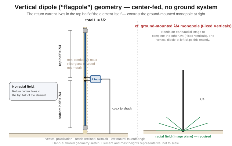
A vertical dipole stands the half-wave element on end: a non-conductive mast — fiberglass or wood, never metal, since a conductive support would short or badly detune the element — carries a full λ/2 wire or tube, fed at its geometric center exactly as a horizontal dipole is, with the current balun of Vol 2 at the feedpoint and the coax routed down alongside the non-conductive support to ground level. Nothing about the electrical structure differs from Vol 1’s canonical half-wave element; only the orientation changes, and that single change in orientation is what makes the variant worth its own section.
4.5.2 No radials required — and why that is the killer feature
The comparison worth drawing explicitly is against a quarter-wave ground-mounted monopole (the subject of the hub’s Fixed Verticals dive), because the two antennas are often confused and the difference is exactly the vertical dipole’s selling point. A quarter-wave monopole is, electrically, half a dipole working against its own mirror image in the earth — Vol 1’s closing line noted that “even a vertical monopole is half of one working against its image” — and that image only exists if the ground beneath the antenna behaves like a return conductor, which real, lossy earth does poorly without help. The standard fix is an extensive buried or elevated radial field, dozens of quarter-wave wires laid out from the base, built specifically to supply the low-loss image current the ground itself cannot. A half-wave vertical dipole carries no such requirement, because it is not relying on an earth image for its other half at all — the top λ/4 and the bottom λ/4 are both physically present in the wire itself, exactly as they are in a horizontal dipole, and the return current the Vol 1 standing-wave picture describes lives entirely in the top half of the element, not in the ground. Mount the whole thing on a fiberglass mast a few feet off a rooftop, a balcony rail, or bare ground, and it radiates at essentially full efficiency with no radial system, no ground rods, and no counterpoise to plan, bury, or maintain.
This is not a theoretical nicety; it is the entire reason a family of commercial “no-radial” HF verticals exists and is marketed explicitly on that basis. The GAP Titan DX and GAP Eagle DX (GAP Antenna Products) are real, current, mid-to-premium-tier products (typically several hundred dollars) built and sold precisely as elevated-feed vertical dipoles that require no ground radials — GAP’s own literature states this directly, explaining that raising the feed away from the earth removes the ground-loss penalty a low-mounted vertical would otherwise take, which is the commercial expression of exactly the physics above. (A precise note on what GAP actually builds: these are trap-free, linear-loaded designs — no lossy LC traps — but they are asymmetric structures, a linear-loaded upper radiator over a short skirt plus three or four rigid elevated counterpoise rods, not the textbook symmetric two-equal-λ/4-legs center-fed half-wave the SVG above idealizes. What they genuinely deliver is a no buried-ground-radial antenna — the small elevated counterpoise is built into the product, not laid in the earth — which is the practical selling point, even though the electrical structure is a real-world compromise rather than a perfect symmetric dipole.)
4.5.3 Polarization, pattern, and where it wins
Vol 3 §2 already flagged the geometric consequence of standing the element on end: the figure-8/circle assignment that governs a horizontal dipole’s azimuth-versus-elevation pattern swaps. Where a horizontal dipole’s azimuth pattern is the figure-8 (broadside maxima, end nulls) and its elevation pattern (absent ground effects) would be the circle, a vertical dipole’s azimuth pattern is the omnidirectional circle and its figure-8 lies in the vertical plane — maximum radiation broadside to the (now vertical) wire, which means maximum toward the horizon, and a null straight up along the wire’s own axis. That reassignment is the source of every practical advantage the vertical dipole offers: omnidirectional azimuth coverage with no need to orient the antenna toward a favored direction, and a naturally low takeoff angle built into the orientation itself rather than earned by hoisting a horizontal dipole to a half-wavelength or more, as Vol 3 §6 required. The polarization is, correspondingly, vertical rather than horizontal.
This combination — omnidirectional coverage, an inherently low takeoff angle, and no ground system — is exactly the profile that wins for DX work from a restricted footprint: an apartment balcony, a small urban lot with no room for a half-wavelength of horizontal wire, a portable or field-day setup where a single non-conductive mast is all that is practical to bring, or any situation where a horizontal dipole’s real-estate demand (Section 3’s whole reason inverted-Vs exist) simply cannot be met. It gives up the modest broadside gain advantage a horizontal dipole enjoys at good height, and it gives up the ability to null out an unwanted direction, but for many restricted-space and DX-first installations neither of those costs matters as much as “it fits, and it needs no ground system.” Classic implementations extend the same idea to specific bands and forms: an end-fed half-wave with a sleeve choke (the W2DU-style configuration, where the coax shield itself forms an insulated quarter-wave sleeve through a series choke, making the outside of the sleeve effectively the second λ/4 of the vertical element) is how most commercial “no-radial” HF end-fed verticals achieve the same electrical trick without a center feedpoint halfway up the mast; on 2 m, the roll-up Slim Jim and J-pole (covered in the hub’s Portable & Mobile Monopoles dive) are vertical half-wave radiators fed through a parallel quarter-wave matching stub rather than a center gap, but they share the same “no ground plane needed” property for exactly the reason developed here.
Buy note. Beyond the GAP Titan DX ($590) and Eagle DX ($500) cited above as the clearest “no-radial vertical dipole” commercial examples (mid-to-premium tier, multi-band, trap-free linear-loaded designs with a small built-in elevated counterpoise rather than buried radials) — note there is no dedicated single-band no-radial vertical-dipole product on the market; both exemplars are inherently multi-band — the single-band, single-wire end-fed-half-wave products sold widely for portable and DXpedition use — commonly deployed vertically off a fiberglass push-up mast — achieve a closely related result through the end-fed-with-49:1-unun approach rather than a true center feed; both routes land on the same “no radial field” outcome for different topological reasons, and the deep comparison of the two approaches, with current models and prices, belongs to Vol 5.
4.6 Comparative pattern and use-case summary
Section-by-section prose is the right place to derive why each variant’s impedance and pattern move the way they do; a single figure that puts all four shapes on the same axes, next to the Vol 1–Vol 3 reference, is the right place to see how much and in which direction. The figure below is a schematic comparative overlay — each curve normalized to its own peak, so the comparison is shape and symmetry, not relative gain — built from the same cosine-family pattern functions this dive has used throughout, rather than a fresh NEC sweep of every variant at every possible geometry (apex angle, slope angle, and height all shift the real pattern continuously, exactly as Sections 3–5 described).
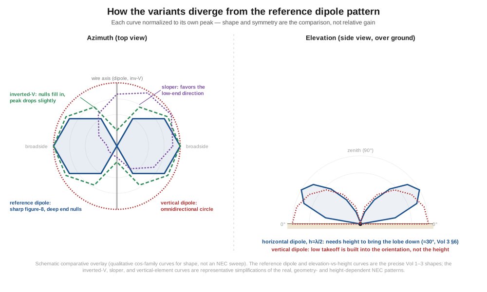
Reading the azimuth panel against the reference dipole’s sharp figure-8: the inverted-V’s curve is the same broadside-favoring shape with its once-deep end nulls filled in and its peak very slightly rounded off, exactly the “softened figure-8” Section 3’s table quantified. The sloper’s curve breaks the dipole’s front-back symmetry outright, becoming a single skewed, favored-direction lobe with a weaker but nonzero response behind it — the geometric signature of the low-end directivity Section 4 described. The vertical dipole’s curve collapses to a perfect circle, the clearest and simplest divergence of the four: azimuth orientation stops mattering entirely. The elevation panel isolates the property Section 5 built its DX case on: the reference horizontal dipole at h = λ/2 (from Vol 3 §6) shows a lobe that has to be earned by height, peaking at a middling ~30° with nulls at both the horizon and the zenith, while the vertical dipole’s element pattern is built low and wide from the geometry alone — maximum right at the horizon, tapering only at the zenith — with no height dependence in the mechanism at all.
The practical decision the four variants boil down to is a short one. Reach for a folded dipole when the bandwidth problem is the one you are solving (80 m coverage, or any application, like FM/TV reception, that wants one wideband element instead of a retune) and you can accept the extra conductor and a 4:1 balun. Reach for an inverted-V when a single mast is the constraint that matters most — which, on an ordinary residential lot, is most of the time — and a modestly softened pattern and a percent of gain are an acceptable trade for not needing a second support. Reach for a sloper (full or half) specifically when a tall tower is already standing for another purpose and a cheap, single-band, favored-direction antenna can ride along on it; do not build a tower for this reason alone. Reach for a vertical dipole when the footprint for a horizontal wire simply is not available, when omnidirectional coverage is worth more than a favored direction, or when a ground/radial system is impractical to install — the restricted-space and portable-DX case that closes out this volume.
4.7 Where this volume hands off
This volume took the clean, straight, horizontal half-wave reference of Vols 1–3 and bent it into the four shapes a real installation most often needs. The folded dipole steps the feedpoint impedance up by a derivable, transmission-line-mode-and-antenna-mode factor of 4× — to roughly 280–300 Ω — while leaving the pattern and gain essentially unchanged and buying 2–3× the SWR bandwidth of a thin-wire element, at the cost of a second conductor and a 4:1 balun; it is the antenna behind both wideband amateur 80 m dipoles and the twin-lead FM antenna in every stereo box ever sold. The inverted-V trades apex angle for a single-mast footprint, sliding the feedpoint resistance from 73 Ω down toward a natural 50 Ω match near α ≈ 90° while softening the figure-8’s nulls and giving up a fraction of a dB of gain — the antenna most amateurs actually mean when they say “dipole.” The sloper, in its full and half forms, trades the flat dipole’s front-back symmetry for a directivity lift of a few dB toward the low end, at the cost of tower dependence and (for the half-sloper) a fundamentally different feed topology built on the tower’s own ground system rather than a balanced pair of arms. The vertical dipole reassigns the figure-8/circle pattern split entirely, trading horizontal directivity for omnidirectional azimuth coverage and a naturally low takeoff angle with no ground or radial system required at all — the configuration that wins specifically where a horizontal dipole’s real-estate demand cannot be met.
Every variant in this volume is still, underneath its geometry, the half-wave element Vol 1 built from first principles, fed by the balun theory Vol 2 developed, and radiating the pattern family Vol 3 worked out for the straight case — bending the wire changes the numbers, not the physics. Vol 5 closes out the single-band dipole dive with the hands-on side of all five volumes: a step-by-step DIY build (including the specific construction differences a folded dipole, an inverted-V, a sloper, and a vertical dipole each demand), the trim-and-sweep NanoVNA tuning loop, the full commercial-buy survey this volume’s brief buy notes only sketched, and weatherproof deployment.
4.8 Resources
- ARRL Antenna Book (25th+ ed.), the dipole and inverted-V chapter and the folded-dipole and sloper sections — the canonical amateur reference for the apex-angle-versus-impedance data and the sloper/half-sloper distinction used throughout this volume.
- Balanis, Antenna Theory: Analysis and Design (4th ed.), §9.5 — the transmission-line-mode/antenna-mode derivation of the folded dipole’s 4× impedance step-up.
- Stutzman & Thiele, Antenna Theory and Design (3rd ed.) — complementary treatment of folded-element and bent-wire antenna impedance.
- Sevick, Transmission Line Transformers (5th ed.) — the current-balun theory (Vol 2) that the folded dipole’s 4:1 match and the sloper’s feedpoint balun both rely on.
- GAP Antenna Products technical literature (Titan DX, Eagle DX) — the manufacturer’s own account of the elevated-feed, no-radial vertical-dipole design principle cited in Section 5.
Comments (0)