Portable & Mobile Monopoles · Volume 5
DIY Build, Commercial Buys & Deployment
A complete 2 m roll-up J-pole build worked honestly from twin-lead's real velocity factor — the detail most published recipes skip — the NanoVNA tuning workflow that separates the length knob from the match knob, a ranked and dated commercial-buy survey spanning every family this dive covers, the companion gear a portable station depends on, and the gotchas that catch first-time builders
5.1 About this volume
The first four volumes of this dive built the portable-and-mobile monopole family from first principles and left each member of it, deliberately, as a documented compromise: the handheld’s missing counterpoise and the size/efficiency ceiling every short antenna runs into, the vehicle roof’s electrically-generous VHF/UHF ground plane against its electrically-tiny HF one, the loaded and tap-tuned portable HF verticals that trade physical height for a real efficiency penalty, and — Vol 4’s own territory — the J-pole and Slim Jim’s matching-stub transmission-line transformer and the feed-tap impedance curve that sets a 50 Ω point somewhere along it. This volume is where that theory lands on a spool of twin-lead, a handful of ferrite beads, and a NanoVNA. It closes the dive the same way the companion Fixed Vertical Monopoles and Single-Band Dipoles dives close their own five-volume arcs: a complete DIY build with real, verified part numbers; a ranked, dated commercial-buy survey spanning every family this dive has covered; the companion gear the whole portable-and-mobile category depends on; and the myths that cost an operator a full grade of signal report.
The DIY build is the canonical cheap backpack VHF antenna: a 2 m roll-up J-pole built from 300 Ω twin-lead, chosen because it is the antenna every SOTA and POTA activator eventually builds, because it rolls into a package smaller than the radio that feeds it, and because — done honestly — it out-performs most of the “high-gain” commercial rubber ducks this dive’s earlier volumes warned against. Vol 4 already derived why the matching stub works as a transmission-line transformer and why the feed tap sets the impedance; this volume does not re-derive that theory. What it adds is a detail nearly every roll-up J-pole recipe circulating online gets wrong or simply omits: twin-lead is not free space, and it is not a single wire either — the antenna’s two sections are governed by two genuinely different physical mechanisms, and cutting both to the same “twin-lead shortening factor” is the single most common reason a first build lands off-frequency by more than a quick trim can fix. Section 3 works that arithmetic in full, with the assumed velocity factor stated and justified rather than asserted.
Section 4 turns the cut antenna into an on-frequency one with a NanoVNA, using a two-knob workflow that mirrors the structure the sibling dives established: here, radiator length sets the resonant frequency and feed-tap position sets the impedance match, and the two must be adjusted one at a time or neither converges cleanly. Section 5 is the commercial-buy survey — real, current, dated products at three price tiers across every family this dive covers: handheld upgrade whips, roll-up J-poles, VHF/UHF mobile whips, HF mobile whips and screwdriver antennas, and portable HF verticals. Sections 6 and 7 round out the practical picture, and Section 8 closes the whole five-volume dive.
One housekeeping note before the parts list, carried forward from every DIY volume in this hub: every price, part number, and product below was checked against a live vendor page, manufacturer datasheet, or manufacturer’s own online store as of late July 2026, and is marked accordingly. Two figures in the source material this dive’s migrated seed carried forward turned out to be wrong on inspection and are corrected here rather than repeated: the Elecraft AX-1’s dimensions, bands, and weight (Section 5 has the corrected numbers, verified directly against Elecraft’s own current listing), and the migrated seed’s own build cost, which quoted ”~$15 total” in prose while its own parts table summed to roughly double that. Section 2’s table is worked honestly from scratch at current prices, and the number it produces is whatever it is — not a headline chosen to sound impressive. Where a specific price or availability could not be confirmed from a live source in this session, that is stated explicitly with the best available reference point; a hedged approximate figure beats a fabricated precise one.
5.2 DIY build — the bill of materials
This is the roll-up J-pole every backpack VHF/UHF station eventually carries: a resonant 2 m half-wave radiator fed through a quarter-wave matching stub, both cut from a single run of 300 Ω twin-lead, with a common-mode choke at the coax transition and a storage pouch that turns the whole thing into something you forget is in the bag. Budget 45–60 minutes of bench work plus the sweep-and-trim loop of Section 4.
Table 1 — 2. DIY build — the bill of materials
| Part | Specification | Source (verified) | Price (late July 2026) |
|---|---|---|---|
| 300 Ω twin-lead | 18 AWG stranded copper-clad steel, window-style parallel line, 0.88 nominal velocity factor (275 Ω actual impedance per the datasheet), sold by the foot; 6 ft cut per antenna | DX Engineering DXE-LL300 — verified live listing, $0.77/ft | $4.62 |
| Ferrite choke cores | 8× solid one-piece round cable core (thread-through, not a hinged snap-on — see the construction note below), Fair-Rite mix 43, 0.312 in. ID (clears RG-316 and RG-8X with room to spare), 113 Ω @ 100 MHz | Fair-Rite 2643625002 — verified live DigiKey listing, $0.89 each (single-unit); $0.62 each at the 10-piece break | $7.12 single-unit, or $6.21 for a 10-pack with two spares (a marginal $4.96 for the 8 this build uses) |
| Coax pigtail | ~3 ft (1 m), RG-316 or similar, terminated in a BNC or SMA connector to match the radio (BNC for most Kenwood/Yaesu-style HTs, SMA for Baofeng/Quansheng-style), bare leads at the antenna end for a direct solder to the feed tap | Generic — no single canonical SKU; any quality RF pigtail assembly works | ≈$12 |
| Solder and flux | Standard 60/40 rosin-core solder plus paste flux | Hardware/electronics store | ≈$3 |
| Self-amalgamating tape | 3M Scotch 130C | Widely stocked | ≈$9 |
| Vinyl overwrap tape | 3M Super 33+ | Widely stocked | ≈$6 |
| Heat-shrink tubing | Assorted 3–12 mm | Generic | ≈$3 |
| Storage pouch | Small zippered pouch, or a length of 1.5 in. PVC pipe with end caps, ~12 in. | Generic | ≈$5 |
| Subtotal, consumables | ≈$49.74 | ||
| NanoVNA | 10 kHz–1.5 GHz+, 4 in. touchscreen, SOLT calibration kit, USB-C | Nooelec NanoVNA-H4 — verified on manufacturer site | $124.95 (one-time tool cost, not consumed per build; the identical price point the sibling Fixed Vertical Monopoles and Single-Band Dipoles dives independently verified) |
Reading the table, and reconciling the migrated seed’s own arithmetic error. The consumables total is roughly $50, not the ”~$15” figure the migrated chapter’s prose asserted while its own parts table summed to about double that — this build has never been a $15 antenna, and the honest number, worked from scratch at today’s prices, is a bit under $50. That is still remarkably cheap for what it out-performs: a $50 roll-up J-pole reliably beats every “high-gain” rubber duck this dive’s earlier volumes catalogued, and it is well inside the price of even the budget tier of Section 5’s commercial handheld whips once you account for the fact that a J-pole, hoisted a few meters up, is doing a fundamentally different job than a handheld’s helical stub.
The twin-lead line is the one part worth a sourcing note. The classic recipe material — plain flat “TV/FM” 300 Ω twin-lead, historically a RadioShack house-brand item — is now largely discontinued at retail; what remains in that exact form is old surplus stock on eBay and Amazon with no reliable published velocity factor, which is precisely the kind of unverifiable-spec part this hub’s DIY sections avoid citing. DX Engineering’s DXE-LL300 window-style ladder line is the current, live, well-documented substitute: it publishes an exact velocity factor (0.88 nominal) and construction (18 AWG stranded copper-clad steel), which Section 3’s arithmetic depends on. The tradeoff is mechanical, not electrical — window line’s semi-rigid plastic web rolls into a looser coil than the classic foam-filled flat twin-lead did, so “rolls up into a package the size of a banana” becomes, honestly, closer to the size of a large orange. It still fits in the storage pouch above, and it is still dramatically smaller than a rigid aluminum J-pole. The datasheet also states the line is “not suitable for use above 30 MHz” — that caveat is about loss when the line carries a matched signal over a long run as a feedline; here it is doing a fundamentally different job, as a short lumped radiating structure a few wavelengths long at most, not a multi-wavelength transmission-line run, so the 30 MHz feedline rating does not disqualify it from this application.
The ferrite choke is the other line item worth flagging: this is the same Fair-Rite 2643625002 part number and roughly the same total the migrated seed’s own BOM cited, and the price checked out against a live DigiKey listing — one of the few numbers in the original chapter that survived verification unchanged. The part’s form, however, did not: it is a solid thread-through core, not the snap-on the seed material implied, and that single fact reorders the build sequence in §3.
5.3 DIY build — the twin-lead arithmetic and construction
The dimensions, worked honestly. Design center is 146.000 MHz, mid-band on 2 m and close enough to the 146.520 MHz national FM simplex calling frequency that the whole build sits comfortably inside the passband either way. Free-space wavelength at 146.000 MHz is λ = c/f = 2.0534 m (80.84 in). A naive roll-up recipe applies one shortening factor to the whole antenna and calls it done; the honest version recognizes that the J-pole’s two twin-lead sections are two different physical objects, and each has its own reason to be shorter than its free-space figure:
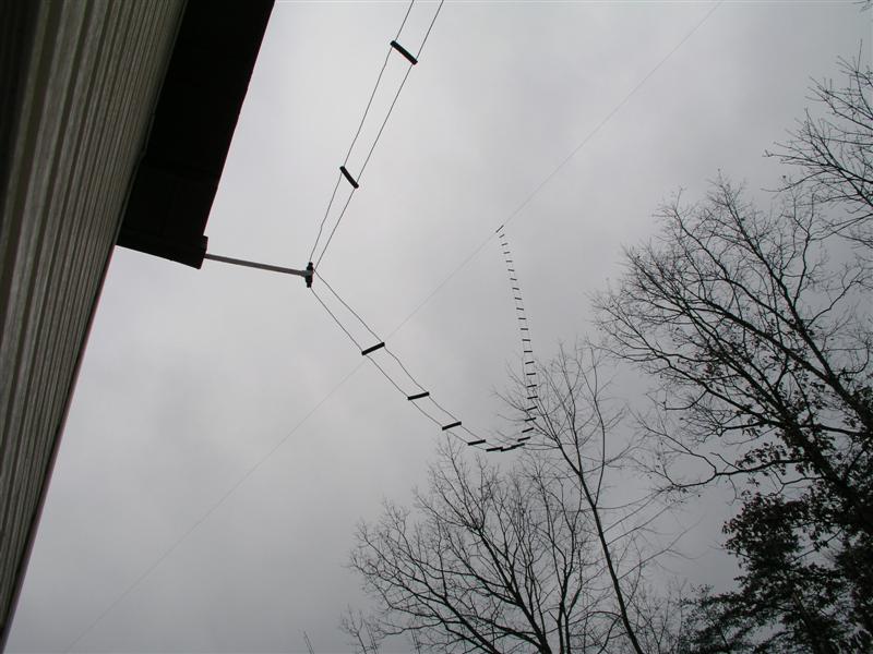
The matching stub is a genuine shorted transmission line, and its physical length is governed by the twin-lead’s own guided-wave velocity — the same velocity factor that sets the propagation speed of any signal traveling down that line. DXE-LL300’s datasheet states a nominal VF of 0.88 (against a stated actual impedance of 275 Ω, not quite the nominal 300 Ω — a normal manufacturing-tolerance footnote, not a design problem). A shorted quarter-wave stub’s physical length is L = 0.25 × λ_freespace × VF, giving 0.25 × 2053.4 mm × 0.88 = 451.7 mm — call it 452 mm (17.8 in).
The radiator is not a transmission line at all. Above the point where the stub ends, only one of the twin-lead’s two conductors continues — the other is deliberately open-circuited at that point (Figure below) and, above it, carries no current; it is present only as inert dielectric-backed wire riding alongside the live conductor. The radiator is therefore a single-wire end-fed half-wave element, and its physical length is set by the ordinary thin-wire end-effect factor this hub’s dipole dives use throughout — k ≈ 0.95 for wire this thin — not by the twin-lead’s transmission-line velocity factor. That gives L = 0.5 × λ_freespace × k = 0.5 × 2053.4 mm × 0.95 = 975.1 mm — call it 975 mm (38.4 in).
This is the detail most published roll-up J-pole recipes get wrong or simply skip past: they publish a single overall length (commonly “54 inches,” a figure that traces back to classic foam-filled RadioShack twin-lead with a real-world measured VF closer to 0.80–0.83) and a stub tap point, with no wavelength arithmetic shown and no velocity factor stated at all. Copy those inches onto a different twin-lead product — window line at VF 0.88, for instance, this build’s own material — and the stub comes out electrically short: a stub cut to the old 16.5 in figure represents only about 92% of a true quarter-wave in 0.88-VF line, not the full 100% it represented in the lower-VF material the recipe was originally tuned on. The match degrades, the tap-position knob (Section 4) has to work harder to compensate, and a builder with no visibility into why the numbers came out that way has no way to fix it beyond guessing. Working the arithmetic from the actual product’s actual datasheet, as above, is the fix — and it is genuinely no more work than copying a number off a decades-old web page.
Total conductor run, stub plus radiator, is 452 + 975 = 1427 mm (56.2 in) at exact resonance. Buy 6 ft (1.83 m) of DXE-LL300 per antenna: that covers the 1427 mm resonant target, a working margin at the bottom for the short and the tap splice, and — critically — a deliberate cut-long allowance on the radiator only, the same one-directional logic this hub’s other wire-antenna DIY sections apply throughout (a hacksaw or side cutters only ever make something shorter). Cut the radiator to roughly 1015 mm (40 in), about 40 mm over the 975 mm target, and cut the stub directly to its 452 mm target — the stub is not the section you trim in the field; Section 4’s tap-position slide absorbs residual match error there, so headroom belongs on the radiator, where the frequency-setting trim actually happens.
Construction sequence:
Cut the twin-lead. From a 6 ft length, mark the bottom short point, then measure 452 mm up from it for the notch, then continue to roughly 1015 mm past the notch for the as-cut radiator tip (leaving the trim margin above).
Solder the bottom short. At the very bottom, strip both conductors and solder them together — a mechanically solid joint, not a twist. This is the shorted end of the matching stub and the antenna’s one true low-impedance point.
Cut the notch. At 452 mm above the short, cut and separate only one of the two conductors — a clean 3–5 mm gap is enough. The other conductor runs on unbroken, all the way to the open top; the cut conductor’s remnant above the notch is now electrically dead and can be left in place (it adds negligible capacitive loading) or trimmed off entirely to save a little wind resistance and weight — either choice is electrically equivalent.
Make the feed tap. Starting point: roughly 30–40 mm above the bottom short — consistent with both the classic twin-lead recipes and the rigid-element convention Vol 4 established for aluminum-tube J-poles. Strip a few millimeters of insulation from each conductor at this height, on the same face of the line, and solder the coax pigtail’s center conductor to one and the shield braid to the other. This tap position is a starting point, not a final answer — Section 4 finds the real one with a NanoVNA in hand.
Add the choke — and note when. The Fair-Rite 2643625002 is a solid, one-piece core: it has no hinge and cannot be snapped shut around an installed cable, so it must be threaded on, which means it has to go on before either end of the pigtail is obstructed. In practice that means doing this step first, not last: thread all 8 cores onto the coax from its bare (un-terminated) end before you solder the feed tap, then slide them up and cluster them just below the tap once that joint is made. Get the order wrong and the only ways out are desoldering the tap or cutting off the factory connector. (If you would rather keep the freedom to add chokes later, substitute a genuine hinged Fair-Rite “Snap-It” core of comparable mix-43 specification — a different product family with a different part-number prefix — and accept the slightly bulkier package.) This suppresses common-mode current that would otherwise ride the coax shield back toward the radio, skewing the pattern and dragging noise (and a hand gripping the coax) into the match.
Weatherproof. Wrap the bottom short, the feed tap, and the choke cluster in 3M Scotch 130C self-amalgamating tape, then overwrap in 3M Super 33+ vinyl tape — rubber tape alone degrades under UV, vinyl alone does not seal against water, and this build re-tapes easily enough each season that a permanent potted joint is not worth the trouble.
Sweep, trim, and deploy — Section 4, in full.
5.4 Tuning with a NanoVNA — two knobs, not one

The two knobs are genuinely independent, and builders conflate them constantly. Radiator length sets where the antenna resonates — trim the open top and the resonant frequency moves; it does not meaningfully change the impedance at any given feed-tap position. Feed-tap position sets how well the resonant impedance matches 50 Ω — slide the tap up or down the stub and the SWR at whatever frequency the antenna is already resonant at improves or worsens; it does not meaningfully move the resonant frequency. Vol 4 derived why the stub behaves this way as a transmission-line transformer with a position-dependent impedance; this section is the practical consequence: adjust one knob at a time, in the right order, or you end up chasing a moving target with no idea which change caused which effect.
Calibrate first, every time. Run the standard OSL (Open-Short-Load) sequence on the NanoVNA — connect Open, select OPEN; connect Short, select SHORT; connect Load, select LOAD; select DONE and save the calibration to a slot. Do this at the end of whatever cable actually reaches the antenna’s feed tap — ideally right at the tap itself for a build this short, since even a meter of pigtail’s own electrical length matters when the whole antenna is only 1.4 m of twin-lead. A quick Smith-chart sanity check (Open at the far right edge, Short at the far left, Load dead center) confirms the calibration is good before touching the antenna.
Fix the frequency first, with the tap at its starting position. Sweep a span wider than the expected error — 141–151 MHz comfortably brackets the 144–148 MHz band with room on both sides to see where an as-cut-long radiator’s resonance actually sits. Read where the SWR trace dips, not what it reads at 146.000 MHz specifically. A radiator cut to the full 1015 mm as-assembled length (40 mm over the 975 mm target) resonates measurably below the design frequency — the antenna is intentionally too long, exactly as Section 3’s cut-long instruction intended — and needs its open top trimmed down toward the target. Trim a small amount, re-measure, re-sweep; two or three iterations typically converges within a few kHz, the same convergence rate this hub’s other wire-antenna DIY sections report for their own cut-long-and-trim loops.
Then fix the match, with the length now fixed. Once the resonant dip sits within a few kHz of 146.000 MHz, stop touching the radiator entirely and start sliding the feed-tap position instead — unsolder, move the tap point up or down the stub by a few millimeters, re-solder, and re-sweep, watching the SWR at the resonant frequency rather than the frequency itself. Moving the tap toward the short generally lowers the impedance the tap presents; moving it away from the short generally raises it — the exact curve and its steepness are Vol 4’s subject, not re-derived here. In practice, on this geometry, the tap position that converges to a clean match commonly lands somewhere in the 30–45 mm range above the short — close to, but not guaranteed to be identical to, the 30–40 mm starting point Section 3 specified; treat that starting point as a reasonable first guess, not a fixed target.
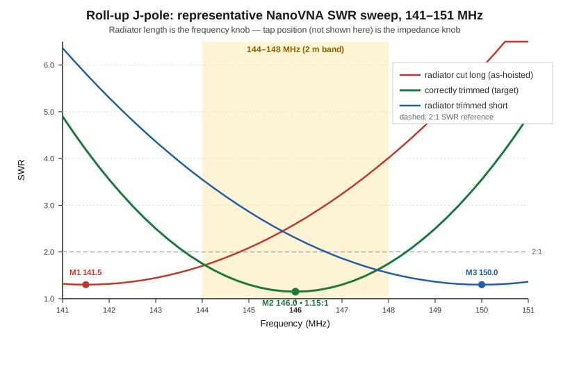
What a good final sweep looks like. At minimum: an SWR minimum at or below roughly 1.3:1 (a well-converged tap position on this geometry commonly lands closer to 1.1–1.2:1); the minimum within about 10–20 kHz of 146.000 MHz; a Smith-chart marker sitting close to the real axis with reactance near zero at the design frequency; and — the same fingerprint every current-choke section in this hub insists on — no shift in the reading when you flex the coax pigtail a few tens of centimeters below the choke cluster. A sweep that moves when the feedline moves means common-mode current is still riding the shield past the choke, which is a choke problem (add cores, or re-check that all eight are actually snapped fully closed) rather than a length or tap-position problem to trim around.
Reading a dip that lands high or low after the two-knob loop should have converged. If the frequency dip refuses to move toward target despite trimming the radiator, suspect the notch (Section 3) — a notch cut in the wrong conductor, or one that didn’t fully separate, leaves both conductors shorted for the full antenna length, which behaves nothing like the intended geometry and will not respond sensibly to trimming. If the match refuses to improve despite sliding the tap across a wide range, suspect the bottom short — a cold-soldered or partially separated short joint changes the stub’s actual electrical length out from under the whole calculation, and no tap position will fully compensate for a stub that isn’t the length Section 3 derived.
5.5 Commercial buys — ranked, with price tiers
For the operator who would rather buy than build — or who wants a factory reference to sanity-check a homebrew antenna against — the following spans every family this dive has covered, checked against live manufacturer or authorized-dealer listings as of late July 2026.
Handheld upgrade whips. The cheapest, highest-return upgrade in this entire volume.
Table 2 — 5. Commercial buys — ranked, with price tiers
| Tier | Product | Bands | Price (late July 2026) | Notes |
|---|---|---|---|---|
| Budget | Nagoya NA-771 | 2m/70cm | $17.95 (verified, BaofengTech, genuine) | 15.6 in. flexible whip, SMA-F, 10 W, rated 2.15 dBi — the honest quarter-wave reference figure, not an inflated marketing number. The universal first upgrade; other retailers list the same genuine part anywhere from about $18 to $30. |
| Mid | Diamond SRH320A | 2m/1.25m/70cm | $43.89 (verified, R&L Electronics) | Tri-band flexible whip, SMA, 13.75 in., 4 dB gain claimed, 10 W. The step up for an operator who also runs 1.25 m. |
| Mid | Diamond RH77CA | 2m/70cm | $22.95–$22.99 (verified, DX Engineering / Ham Radio Outlet, in stock) | Diamond’s own site quotes the older RH771 designation as dealer-priced with no public figure; the RH77CA is the SKU actually stocked at current US retail and is treated here as the RH771’s practical successor. |
A quarter-wave-or-longer whip like any of these, paired with a quarter-wave tiger-tail counterpoise clipped to the radio’s ground shell, is the best handheld antenna system money buys at this price point — a pairing this dive’s earlier volumes already quantified.
Roll-up (and rigid) J-poles. This volume’s own DIY build sits at the budget end of this table by construction.
Table 3 — 5. Commercial buys — ranked, with price tiers
| Tier | Product | Bands | Price (late July 2026) | Notes |
|---|---|---|---|---|
| Budget (DIY) | This volume’s build | 2m | ≈$50 in consumables (Section 2) | Roll-up, twin-lead, requires the Section 4 tuning loop; the cheapest capable option in this table by a wide margin. |
| Budget (commercial, rigid) | Ed Fong DBJ-1 | 2m/70cm | $55 (verified, edsantennas.weebly.com) | Rigid twin-lead J-pole mounted on a 5 ft PVC pipe (not included — Lowe’s item #23990 per the seller’s own instructions); SO-239 or N connector; 75 W max. Not a roll-up — the fixed-installation sibling. |
| Mid (commercial, roll-up) | Ed Fong DBJ-2 | 2m/70cm | $60 (verified, edsantennas.weebly.com) | The commercial roll-up kit: includes BNC, SMA, and SMA-female adapters plus a 6 ft extension cable; 50 W max. Factory-built and factory-tuned — the “I’d rather not solder” answer to this volume’s own build. |
VHF/UHF mobile whips. The vehicle-roof ground plane makes this family the easiest to get right; all three below need an NMO mount (a good default) or an equivalent 3/8-24 base.
Table 4 — 5. Commercial buys — ranked, with price tiers
| Tier | Product | Bands | Price (late July 2026) | Notes |
|---|---|---|---|---|
| Budget | Diamond NR770HBNMO | 2m/70cm | $55.99 (verified, DX Engineering) | 38.2 in., 200 W, fold-over, radialless design (no ground plane dependency the way a bare quarter-wave whip has). |
| Mid | Comet SBB-5 | 2m/70cm | $69.95 (verified, DX Engineering) | 38 in., 120 W, the canonical “good enough for serious use” mobile whip and the most commonly recommended in this class. |
| Premium | Comet CA-2X4SR | 2m/70cm | $71.95 (verified, R&L Electronics) | 40 in., 150 W, higher-gain collinear geometry — the step up for an operator who wants the extra reach on a repeater at the edge of coverage. |
HF mobile whips and screwdrivers. The steepest price curve in this volume, and a genuinely thinning market at the top end.
Table 5 — 5. Commercial buys — ranked, with price tiers
| Tier | Product | Bands | Price (late July 2026) | Notes |
|---|---|---|---|---|
| Budget | MFJ-1640T (40 m) | Single band | $22.95 (verified, mfjenterprises.com) | Center-and-distributed-loaded fiberglass whip on a 3/8-24 base; needs a separate mount and mast. Other single-band MFJ HamTenna whips (1620T for 20 m, etc.) price similarly. |
| Mid | Hustler RM-20 resonator (20 m) | Single band | $45.95–$49.95 (verified, R&L Electronics / Ham Radio Outlet) | Sold per band — one resonator per HF band, swapped on a common mast (MO-2, sold separately, currently $73.99 through DX Engineering — verified, see Vol 3 §2). The classic “swap sticks at a roadside stop” system. |
| Premium | Tarheel Little Tarheel II | 80–10 m continuous | Unconfirmed — dealer quote required | Motor-driven screwdriver coil, compact form factor. The manufacturer posts no list prices (see Vol 3 §5); treat any figure quoted elsewhere as unverified. |
| Premium | Tarheel Model 100A-HP | 80–10 m continuous | Unconfirmed — dealer quote required | 6 ft whip, 1,500 W PEP rated. Manufacturer posts no list prices. |
| Premium | Tarheel Model 200A-HP | 80–10 m continuous | Unconfirmed — dealer quote required | Larger-diameter coil for higher power handling and lower loss than the 100A-HP; 1,500 W PEP rated. Manufacturer posts no list prices. |
A market note worth stating plainly: Scorpion Antennas, long regarded as one of the best-built screwdriver antennas on the market, is out of business as of this writing — the manufacturer’s own site is dead, and the used market (a recent SA-680 sale around $650) is the only path to one now. Hi-Q Antennas remains active at the very top of this market, with its most affordable 80 m-capable model priced around $1,145 before accessories per current dealer listings — not independently re-verified against Hi-Q’s own site this session, but consistent with the premium-tier pricing this whole category commands.
Portable HF verticals. The segment with the widest single correction in this volume.
Table 6 — 5. Commercial buys — ranked, with price tiers
| Tier | Product | Bands | Price (late July 2026) | Notes |
|---|---|---|---|---|
| Mid | Buddistick PRO | 40–6 m | $199.00 (verified, buddipole.com) | Modular vertical: Versahub feedpoint, two aluminum arms, telescopic whip, adjustable coil, 31 ft elevated radial wire on a winder, Cordura carry bag. |
| Mid | Elecraft AX-1 | 20 m and 17/15 m (two switch positions) | $131.95 (verified, elecraft.com, in stock) | Corrected from the migrated seed, which had this entry wrong three ways. Collapsed 6 in. (15 cm), extended 45 in. (115 cm) — not “17 ft.” Bands are 20 m in one switch position and 17/15 m in the other — not “17/15/10 m.” Total weight, antenna plus the supplied 13 ft counterpoise wire, is 3.8 oz (107 g) — antenna 3.2 oz (90 g) plus wire 0.6 oz (17 g) — not “~150 g.” An ATU is not strictly mandatory per Elecraft’s own listing but is described as needed to eliminate “tedious length adjustments” across all three bands, and the KX2/KX3’s built-in ATU is the antenna’s natural pairing; treat it as effectively ATU-required for practical use. At least one UK dealer (Moonraker) lists the AX-1 as discontinued/legacy stock; Elecraft’s own US store shows it in stock at the price above as of this verification — check regional availability before ordering. |
| Mid-premium | Chameleon MPAS Lite | 160–6 m | $360.00 (verified, DX Engineering) | Modular portable system: hybrid micro tapped-coil, telescoping whip, ground spike, counterpoise wire, tripod-mountable. |
| Unconfirmed | Super Antenna MP-1 | 80–2 m (band-dependent on coil/whip configuration) | Not independently confirmed at a US retailer this session | A European dealer (Wimo) lists the tripod-and-radials package at €329.90 including VAT; historical US retail for the base kit has been cited around $220–260, but no live 2026 US price could be pinned down from a public listing in this pass. Confirm current pricing directly with Super Antenna Systems or an authorized US dealer before ordering. |
| Unconfirmed | Wolf River Coils TIA | 80–6 m (coil-dependent) | Not published as a single bundled price on the current site | Wolf River Coils’ own site lists the Mini Pod base, the Silver Bullet coil, and the telescoping whip as separate catalog line items rather than one “TIA kit” price; community and historical references put a complete system (pod, coil, whip, three 33 ft radials) around $150–200, but that figure is not independently re-verified against a current 2026 listing. |
What to avoid. “9 dBi dual-band rubber duck” and equivalent handheld claims — physically impossible at the stated size and length, and the physics behind why belongs to this dive’s earlier volumes, not repeated here. A “multi-band mobile HF whip” advertised without a stated efficiency or a radial/counterpoise requirement is quietly omitting the one number that determines whether the antenna performs or merely radiates something. And — the market-condition note this table makes concrete — the HF screwdriver-antenna segment has genuinely thinned at the top: Scorpion’s exit leaves Tarheel and Hi-Q as close to the only two serious current manufacturers in that specific niche, which is worth knowing before assuming the used market will always have a third option.
5.6 Companion gear
Mast or hoist point. For the roll-up J-pole, the classic deployment is a length of fishing line thrown over a tree branch and hauled up by hand — free, and it works. A Jackite 31 ft telescoping fiberglass pole (collapses to roughly 45 in.) is the step up for a treeless site; historical pricing runs close to $1/ft (roughly $30), though a live current price could not be confirmed from the manufacturer’s own site this session — check jackite.com or an authorized dealer directly. For mobile HF sticks, the mast is sold separately from the resonator (Section 5’s Hustler entry) and the same non-conductive-support-stub logic this hub’s fixed-vertical DIY volume applies at ground level applies here at bumper height: a metal mast bonds the resonator’s base to the vehicle body in an untuned way that a fiberglass or heavy-wall PVC mast section avoids.
Halyard and counterweight. For anything hoisted rather than clamped — the roll-up J-pole chief among them — a length of the same 3/16 in. double-braided Dacron/polyester halyard rope this hub’s other DIY volumes specify (DX Engineering SYN-DBR-187-500, verified live, $85.99 for a 500 ft spool — a 20–30 ft cut is all one antenna needs) resists the stretch nylon rope introduces under sustained tension, which otherwise lets a hoisted antenna sag and detune over a multi-day deployment.
Counterpoise and radial wire. Portable HF verticals (Buddistick, MP-1, Wolf River Coils, Chameleon MPAS Lite) all depend on their supplied or after-market counterpoise wire being actually deployed, not left coiled in the bag — this dive’s earlier volumes already made that point in depth. The same DX Engineering DXE-ANTW-150 insulated 14 AWG stock this hub’s fixed-vertical DIY volume specifies (verified, $49.99 for 150 ft) is a reasonable bulk source if a supplied radial wire is lost or a longer run is wanted for a lower band.
Coax and connectors. RG-316 is the right choice for a short, light, flexible pigtail on the roll-up J-pole and on handheld whips generally — its loss at VHF/UHF over the meter-scale runs this family uses is negligible, and its small diameter and flexibility matter more than its (real, but here irrelevant) higher loss-per-foot compared to RG-8X on longer HF runs. For vehicle-mobile VHF/UHF and HF mobile whips, RG-8X is the standard middle ground; for a permanently mounted vehicle installation with a long run from roof to radio, LMR-240 or better is worth the extra cost. Connector choice should match the radio, not be mixed mid-run: BNC for most commercial and amateur HTs that use it, SMA for the Baofeng/Quansheng-style handhelds that have made SMA the de-facto sub-$50 radio standard, PL-259/SO-239 for HF mobile and most VHF/UHF mobile whips.
Storage. The single most preventable failure mode in this entire family is losing a counterpoise wire, a radial set, or a roll-up antenna’s coax pigtail separately from the antenna itself — a small dedicated pouch or a labeled PVC tube that holds the whole kit together (antenna, choke, pigtail, and any counterpoise wire as one unit) is worth more than any single component upgrade in this table.
5.7 Gotchas and myths
“I’ll just use the same shortening factor for the whole twin-lead antenna” is the single error Section 3 spent the most words correcting, because it is the one that actually changes a build’s outcome: the shorted stub is a transmission line and takes the material’s real VF; the open radiator is a single-conductor end-fed element and takes the ordinary thin-wire end-effect factor instead. Apply the transmission-line VF to the radiator and it comes out too short; apply the thin-wire factor to the stub and the match degrades in a way no amount of tap-sliding fully recovers.
“My SWR is 1.0:1 on the rubber duck, so it’s working fine” is this dive’s own recurring trap, restated for the roll-up build: a low SWR reading is not evidence of high efficiency, only of a well-matched something — sometimes that something is a genuinely resonant, well-radiating antenna, and sometimes it is a lossy internal network quietly burning power as heat. A 1.15:1 sweep on this volume’s finished build, verified with the flex-the-coax check in Section 4, is trustworthy precisely because that check rules out the common-mode-current failure mode that produces a falsely clean-looking number.
“Higher gain numbers on a handheld antenna box mean better performance” — a claim this dive’s earlier volumes already dismantled in depth and worth restating briefly here because Section 5’s buy table is exactly where a shopper encounters it: a physically short helical antenna cannot legitimately claim gain figures that would require a beamwidth no stubby whip geometry can produce. Buy on physical length and connector match, not on the printed dBi number.
“A roll-up antenna is a compromise, so a rigid J-pole is always better” overstates the mechanical tradeoff. Electrically, a correctly cut and tuned roll-up twin-lead J-pole performs essentially identically to a rigid aluminum-tube J-pole of the same geometry — Vol 4’s feed-tap and matching-stub theory does not care what the conductor is made of. The rigid version wins on wind loading and long-term UV exposure for a semi-permanent field-day installation; the roll-up wins on pack size and setup speed for a backpack. Neither is the “compromised” version of the other.
“Screwdriver antennas are all basically the same” ignores that this specific market has genuinely thinned: Scorpion’s exit leaves a real gap at the upper-mid tier, and Tarheel and Hi-Q occupy different points on the size/weight/price curve rather than being interchangeable. Buying a used Scorpion sight-unseen at a premium price because “it’s the same thing” skips checking whether the specific unit’s coil and motor have survived their first owner’s use.
“Twin-lead is twin-lead — any 300 Ω line will give the same cut lengths” is the sourcing-side version of the VF error: window line (0.88 VF, per DXE-LL300’s datasheet) and classic foam-filled flat twin-lead (measured closer to 0.80–0.83 VF in independent tests) genuinely differ, and a stub cut for one on the assumption it’s the other lands measurably off. Whatever twin-lead a builder actually sources, its own datasheet’s velocity factor — not a number copied from an unrelated recipe — is the one to use in Section 3’s arithmetic.
“The tap position and the radiator length are basically the same adjustment” is the conflation Section 4 exists to prevent. They are independent, they interact only weakly, and adjusting both at once when a sweep looks wrong makes it impossible to tell which change produced which effect. Fix frequency first with the radiator, fix match second with the tap, in that order, every time.
5.8 Where this volume — and this dive — hands off
This volume closed the Portable & Mobile Monopoles dive by putting the first four volumes’ theory on a spool of twin-lead, a handful of ferrite beads, and a NanoVNA. It gave a complete, real-parts bill of materials for a 2 m roll-up J-pole — a verified $4.62 in DX Engineering window line, a verified $7.12 in Fair-Rite snap-on chokes, and a consumables total of roughly $50 that honestly reconciles the migrated seed’s own internal contradiction between its “$15” headline and its “$32” table. It worked the twin-lead velocity-factor arithmetic that most published roll-up recipes skip past — a genuine transmission-line VF (0.88, DXE-LL300’s own datasheet) for the shorted matching stub, and the ordinary thin-wire end-effect factor (0.95) for the single-conductor open radiator — producing a 452 mm stub and a 975 mm radiator worked from first principles rather than copied from a decades-old web page tuned for different material. It formalized a NanoVNA workflow with two genuinely independent knobs — radiator length for frequency, feed-tap position for match — mirroring the two-knob structure the sibling Fixed Vertical Monopoles dive established for its own build. It surveyed the commercial alternative across every family this dive covers, from a verified $17.95 Nagoya NA-771 up into the screwdriver-antenna tier, correcting the migrated seed’s three-way-wrong Elecraft AX-1 entry along the way and flagging, rather than inventing, every price that could not be confirmed from a live 2026 listing — including the whole Tarheel line, whose manufacturer publishes no figures at all. And it closed with the companion gear and the myths — the VF-conflation error, the low-SWR trap, the inflated-gain handheld claim, and the thinning screwdriver-antenna market — that separate a portable antenna that performs from one that merely transmits something.
Zooming out, this volume is also the last of the five that make up the Portable & Mobile Monopoles dive. Vol 1 established the family’s defining problem — the handheld’s missing counterpoise, and the size/efficiency ceiling that governs every short antenna in this hub. Vol 2 took ownership of the vehicle-mobile case, VHF/UHF against a generous roof ground plane and HF against an electrically tiny one. Vol 3 surveyed the portable HF vertical family — MP-1, AX-1, Buddistick, Wolf River Coils — and the loaded-antenna efficiency penalty each one accepts for a fraction of a full-size whip’s height. Vol 4 covered the J-pole and Slim Jim’s matching-stub transmission-line theory and feed-tap impedance curve in full. And this volume put all of it on a bill of materials, a construction sequence, a NanoVNA workflow, and — for the reader who would rather buy than build — a dated shopping list spanning the whole family.
The portable-and-mobile monopole is this hub’s answer to the question the fixed-vertical dive never has to ask: what do you do when a permanent radial field, or a permanent installation of any kind, simply isn’t an option. The companion Fixed Vertical Monopoles dive picks up the vertical-antenna story where a real ground system is available, and the Single-Band Dipoles dive’s own DIY-and-buy closing volume is the template this volume followed for its own structure. The matching-network theory this dive touched at its edges — the full transmission-line-transformer treatment behind Vol 4’s stub analysis, and the antenna-tuner alternative for the HF mobile and portable-vertical entries in Section 5 — lives in this hub’s dedicated matching-network dives; the measurement theory behind the NanoVNA workflow Section 4 used lives in this hub’s measurement cluster. This volume points to both rather than reproducing them, consistent with the whole hub’s cross-linking discipline.
5.9 Resources
- ARRL Antenna Book (25th+ ed.), the J-pole and mobile-antenna construction chapters — the canonical amateur reference for build dimensions and matching-stub theory.
- DX Engineering — https://www.dxengineering.com — the source verified for the DXE-LL300 twin-lead, DXE-ANTW-150 radial wire, SYN-DBR-187-500 halyard rope, Diamond NR770HBNMO, Comet SBB-5, and Chameleon MPAS Lite prices and specifications in Sections 2, 5, and 6.
- Fair-Rite Products — https://www.fair-rite.com and DigiKey’s verified listing for part 2643625002 — the mix-43 solid round-cable-core specification and price cited in Section 2.
- Nooelec — https://www.nooelec.com — the source verified for the NanoVNA-H4 specification and price in Section 2, the same tool and price point the sibling Fixed Vertical Monopoles and Single-Band Dipoles dives independently verified.
- Ed’s Antennas (Dr. Ed Fong) — https://edsantennas.weebly.com — the source verified for the DBJ-1 and DBJ-2 current prices and specifications in Section 5.
- BaofengTech, R&L Electronics, GigaParts, and Ham Radio Outlet — the sources verified for the Nagoya NA-771, Diamond SRH320A and RH77CA, Comet CA-2X4SR, MFJ-1640T, and Hustler RM-20 prices in Section 5.
- Tarheel Antennas — https://www.tarheelantennas.com — the current model range for the Little Tarheel II, Model 100A-HP, and Model 200A-HP. Note that the site publishes no prices; the Section 5 entries are marked unconfirmed accordingly.
- Elecraft — https://elecraft.com — the source verified for the corrected AX-1 dimensions, weight, bands, and price in Section 5.
- Buddipole — https://www.buddipole.com — the source verified for the Buddistick PRO current price and package contents in Section 5.
- NanoVNA-Saver (PC companion software) — https://github.com/NanoVNA-Saver/nanovna-saver — free, and the natural next step once Section 4’s on-device sweep confirms the two-knob tuning has converged; it logs and overlays sweeps, the easiest way to compare an as-cut-long and a final trace like the one in this volume’s figure.
- The hub’s dedicated matching-network dives (BALUNs & UNUNs, Antenna Tuners) — the full transmission-line-transformer theory behind Vol 4’s stub analysis and the tuner alternative to a resonant cut.
- The hub’s measurement cluster (NanoVNA deep dive, other analyzers, power/SWR measurement) — the full instrument-level treatment behind the workflow Section 4 used at the level this dive needed.
Comments (0)