Portable & Mobile Monopoles · Volume 3
Mobile & Portable HF
Loaded whips, screwdrivers, and the counterpoise you must deploy — ham-stick geometry and the physical band-swap workflow, a single reconciled efficiency-by-band table, screwdriver-antenna mechanics and price reality, capacity hats, the backpack-HF survey (MP-1, AX-1, Buddistick/Buddipole, Wolf River Coil), and why a low SWR without a counterpoise is a lie
3.1 About this volume
Vol 1 of this dive built the loading physics every shortened HF radiator answers to — base, center, and top loading; the current-taper argument for why loading position sets efficiency; the R_rad ∝ (h_eff/λ)² collapse; and the Chu-Harrington bound tying a small antenna’s bandwidth to its efficiency with no escape clause. This volume is where those numbers stop being abstractions and start being the actual antennas a mobile or backpack HF operator screws onto a mount: single-band ham-sticks, the Hustler mast-and-resonator system, screwdriver antennas that trade a fixed loading position for a continuously variable one, and the compact backpack verticals — MP-1, AX-1, Buddistick/Buddipole, Wolf River Coil — SOTA and POTA operators carry to a summit or a park bench.
The organizing fact of the whole volume, and the reason it closes on a counterpoise section rather than a commercial-buys table, is that every one of these antennas is a shortened, loaded monopole with an ad-hoc ground reference. Vol 1 and the companion shortened-and-loaded-vertical volume in the fixed-vertical dive both establish that a monopole’s radiation resistance is tiny to begin with and falls further as the structure shrinks below a quarter-wave — so the loss resistance in series with it, wherever it comes from, dominates the efficiency bookkeeping far more than it would for a full-size antenna with a comfortable margin of R_rad to spare. A fixed vertical fights that loss with a radial field it builds once and leaves in the ground. A mobile or portable vertical has no such luxury — its “ground” is a vehicle body of uncertain bonding, a folding tripod, or the operator’s own two feet on damp grass — and the honest treatment of that problem is this volume’s spine. Sections 2–6 work through the vehicle-mobile family (ham-sticks, the screwdriver alternative, capacity hats); §7 surveys the backpack-portable family; §8 is the counterpoise argument that ties all of it together and explains why a satisfying SWR reading, alone, tells you nothing about whether any of this actually radiated.
One number is worth stating up front because it recurs throughout: the migrated seed material for this dive carried two efficiency-by-band tables for the ham-stick family that do not agree, because one silently swaps antenna types as the band changes while the other holds the type fixed. §3 does the honest reconciliation — one table, one antenna, one stated set of assumptions — rather than presenting either uncritically or splitting the difference by eye.
3.2 Ham-sticks and single-band loaded mobile whips
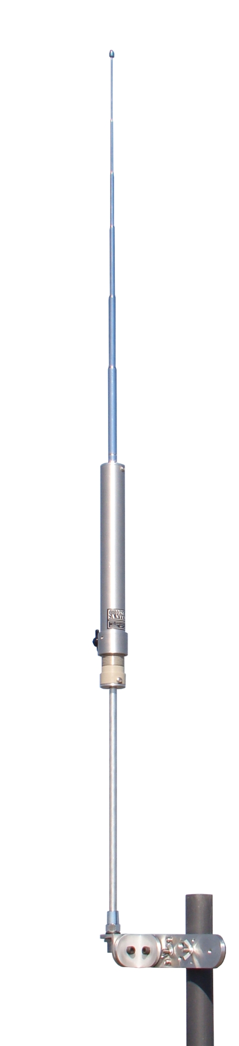
A “ham-stick” — the generic term for the entire class, regardless of which company actually built the specific one on your mount — is the simplest possible embodiment of a shortened, loaded monopole: a loading coil wound on a form near the base, a fiberglass rod running most of the physical length above it with a copper strap or wire helix bonded along part of that length as distributed loading, and a stainless-steel tip section that telescopes or threads for fine trim. Total length runs a little over 7 ft (roughly 2.1–2.2 m) on the lower-band sticks and shrinks somewhat on the higher bands, where less physical structure is needed to reach an appreciable fraction of a quarter-wave. The base terminates in a 3/8″-24 threaded stud — the de-facto mobile-HF mounting standard since the format’s earliest days, and why a stick from three different manufacturers all thread onto the same mount without adapters.
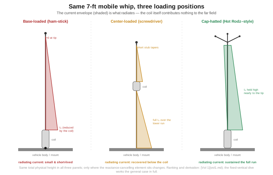
Electrically, this geometry is base-loaded in the sense Vol 1 defines the term: the coil sits in the bottom third of the physical structure, ahead of most of the radiating wire, so the current reaching the fiberglass rod above it has already been reduced by the same reactive-network effect that puts the coil there, and it tapers the rest of the way to zero at the tip over a physically short run. That is the worst-performing loading position the ranking establishes, and a ham-stick is not a design accident that landed there — it is the mechanically simplest, cheapest way to build a single-band mobile HF antenna, and §3’s efficiency penalty is the price of that simplicity. Figure 1 makes the current-taper argument concrete for this geometry, set against the two better-performing positions the rest of this volume reaches for when a ham-stick’s own efficiency isn’t good enough.
3.2.1 Why each stick is single-band
A ham-stick’s coil, rod length, and copper-strap loading are all cut for one design frequency, and the tunable tip gives only a small trim range around that point — enough to move within a single amateur band, not enough to jump to an adjacent one. This follows directly from how much reactance the coil has to cancel: an 80 m stick’s coil carries far more inductance than a 10 m stick’s, because Vol 1’s R_rad ∝ (h_eff/λ)² relation and its accompanying reactance-cancellation requirement both scale with how far short of resonance the bare physical structure falls, and that shortfall is enormously larger at 80 m than at 10 m for the same physical stick length. A single stick’s inductance, once wound, is fixed; retuning further than the tip’s trim range means rewinding or replacing the coil, which is exactly the operation Hustler and the other manufacturers package as a swap-in resonator rather than asking the operator to attempt in the field.
The operational consequence is the multi-stick mobile station: a serious HF-mobile operator running ham-sticks typically owns one stick per band worked (80, 40, 20, and 15 or 10 m is a common four-band loadout) and physically exchanges them at the mount between bands. A plain 3/8″-24 stud makes this a wrench-and-thirty-seconds operation; a spring-loaded quick-disconnect adapter cuts that to a few seconds without tools, at the cost of a little contact resistance and one more joint to keep clean. Either way it is a stop-the-vehicle operation — you are not retuning at a stoplight — which is the entire reason the screwdriver antenna (§5) exists as a premium alternative.
3.2.2 The Hustler mast-and-resonator system
Hustler (built today by New-Tronics Antenna Corporation of Mineral Wells, Texas, which purchased the Hustler line in 1985) sells the same electrical idea as two separable parts rather than one fixed stick: a fiberglass mast — the MO-2, 54″ overall with a fold-over point 27″ above the base for low-clearance bumper or hitch mounts, currently $73.99 through DX Engineering — and a family of single-band resonators that thread onto the mast top, each a self-contained coil-and-tip assembly for one band. A Hustler RM-40 standard resonator (40 m) currently lists at $63.99; the “Super” resonator line costs modestly more for a slightly larger coil and wider usable bandwidth, a genuine benefit on 75/80 and 40 m where standard resonators can be narrow enough to need retrimming across a wide phone band.
The practical difference from a one-piece ham-stick is entirely in swap logistics: a Hustler operator keeps one mast permanently mounted and carries a bag of resonators, changing bands by unscrewing one and threading in another, with the mast itself never leaving the vehicle. A four-band loadout (mast plus four standard resonators) runs to roughly $330–400 at current DX Engineering pricing — noticeably more than the historical figure sometimes quoted for a comparable kit, so check current listings before budgeting rather than trusting a remembered number.
One brand-lineage note worth correcting: the “Hamstick” name is a trademark of Lakeview Company, Inc. of Anderson, South Carolina — a separate company from New-Tronics/Hustler, not a Hustler-owned sub-brand as some older secondary sources (including this dive’s own migrated seed material) have claimed. The two lines are functionally similar and interchangeable at the mount but come from two independent manufacturers; Lakeview’s site does not publish list prices, and no live 2026 price for a Lakeview Hamstick could be confirmed — treat any figure quoted elsewhere for that brand as unverified.
3.3 The efficiency reckoning by band — reconciling two tables into one
This dive’s migrated seed material carried two efficiency-by-band tables that do not agree, and the reason is worth stating before presenting a corrected one: the first table (framed as “the practical portable antenna” across bands) silently changes which antenna it describes as the band changes — a ham-stick at 80 m, an MP-1-type coil-loaded vertical at 40 m, a full-size telescoping whip at 20 m and above — while the second holds a single ham-stick geometry fixed across all ten bands. Comparing them band-by-band is comparing apples mid-band to oranges; the honest fix is not to average the two but to recognize that only the second is actually answering this volume’s question (one base-loaded ~7 ft mobile whip, across bands), and to rebuild that single table from the physics Vol 1 and the fixed-vertical dive’s loading-position work already established, rather than presenting either source table on its own authority.
The physical picture is the one §2 already set up. A ham-stick’s total physical height is close to constant across the product line — call it h_phys ≈ 2.1 m (7 ft) — while the fraction of a full quarter-wave that height represents grows steadily as frequency rises, because λ/4 itself shrinks. On 80 m that fraction is a little over 10%; by 10 m it is over 80%; on 6 m the stick is actually longer than a full quarter-wave and needs no coil at all — hence the plain fiberglass “6 m whip” in every lineup. Applying R_rad ≈ 160π²(h_eff/λ)² Ω to that shrinking-fraction picture, with the base-loading current taper fixing h_eff = h_phys/2 at every band — the same relation Vol 1 §7 works through for a generic 2 m whip, applied here to this volume’s specific 7 ft stick — gives a radiation resistance running from about 0.27 Ω on 80 m up to about 16 Ω on 10 m.
The loss-resistance side of the ledger has to be equally explicit, because it decides the table rather than footnoting it. It has two components. The coil contributes R_coil = X_L/Q, §4’s own relation, where X_L is set by how much reactance the shortened rod needs cancelled: treating the 7 ft stick as an open-circuited stub of surge impedance Z₀ ≈ 350 Ω (representative for a tapered fiberglass-and-wire mobile whip this diameter), X_L = Z₀·cot(βh_phys) runs on the order of 2,100 Ω on 80 m, falling under 200 Ω by 10 m as less of the rod needs electrically “growing.” At a compact mobile coil’s Q of 100–150 — the bottom of Vol 1 §6’s 100–300 range, because a ham-stick’s coil is the compact, densely-wound kind §4 already describes, not the large-diameter, widely-spaced coil that reaches the top of it — R_coil runs 14–21 Ω on 80 m, collapsing to a couple of ohms or less by 10 m. Vehicle-body/ground-return coupling adds a further 5–20 Ω, largely band-independent, consistent with the range this volume and the fixed-vertical dive’s radial-field volume both cite for a comparably lossy return path. Summed, the two components bracket 15–35 Ω, coil-dominated on 80 and 40 m and ground-dominated from 20 m up as the coil’s own share falls away — the single R_loss bracket the table below actually uses, held constant across rows because its total doesn’t move much even though its composition does.
Running η = R_rad/(R_rad + R_loss) for R_loss = 15–35 Ω against every row’s own R_rad gives the table below directly, with no fitting toward an inherited number. It lands markedly lower than this dive’s own earlier draft of this table on every row, most sharply on 80 and 40 m — and that is the correct direction, not a defect to soften: the widely reported real-world figure for an 80 m mobile whip’s efficiency is low single digits, and this table’s 1–2% is the honest match to that experience, not a comfortable rounding of it.
Table 1 — 3. The efficiency reckoning by band — reconciling two tables into one
| Band | Design freq (MHz) | λ/4 | Physical height as fraction of λ/4 | Reconciled efficiency (feedpoint-referenced) |
|---|---|---|---|---|
| 80 m | 3.75 | 20.0 m | ~0.11 | 1–2% |
| 60 m | 5.36 | 14.0 m | ~0.15 | 2–4% |
| 40 m | 7.15 | 10.5 m | ~0.20 | 3–6% |
| 30 m | 10.125 | 7.4 m | ~0.29 | 5–12% |
| 20 m | 14.175 | 5.3 m | ~0.40 | 10–20% |
| 17 m | 18.118 | 4.1 m | ~0.51 | 16–30% |
| 15 m | 21.225 | 3.5 m | ~0.60 | 20–37% |
| 12 m | 24.940 | 3.0 m | ~0.71 | 26–45% |
| 10 m | 28.500 | 2.6 m | ~0.81 | 32–52% |
| 6 m | 50.250 | 1.5 m | >1.0 (full-size, unloaded) | 85%+ |
Figure 2 plots this table as a single reconciled curve, replacing the two disagreeing bar-shaped figures the migrated source material carried separately.
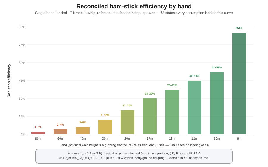
One more reconciliation is owed, this time against this hub’s own material rather than the migrated seed: Vol 1 §8 carries its own “reconciled” efficiency-by-band table, and above 20 m the two disagree by roughly two- to five-fold — widest at 20 m (55–80% there against this table’s 10–20%, better than four times over), narrowing toward 12/10 m (75–90% there against this table’s 26–52%, closer to two times over) as this table’s own fixed-hardware fraction of λ/4 closes in on Vol 1’s near-full-size assumption. That is not an error in either table; the two are answering different questions. Vol 1 §8’s table lets the antenna change with the band — a loaded whip on 80/40 m giving way to a near-full-size or full-size telescoping whip once the physical-size penalty stops being prohibitive at 20 m and up — because that is what a portable operator who owns more than one antenna actually does. This table holds one fixed ~7 ft base-loaded stick across every band, because that is what a mobile operator with a single-band ham-stick collection is stuck with, one stick at a time, on the band that stick is cut for. Both are honestly derived; neither should be read against the other band-for-band without accounting for which antenna each row assumes.
Three assumptions this table rests on need to be said out loud, because each is doing real work in the numbers. First, the efficiency figure is referenced to power delivered to the antenna’s own feedpoint, not to power leaving the transmitter — it excludes coax loss, a lossy tuner network upstream, and connector loss, all of which stack in addition to whatever this table says. Second, the loss-resistance figure (15–35 Ω) is the sum of a coil term and a ground term worked out separately above, not a single measured or fitted number — the two cannot be cleanly separated from the outside once summed, because a hotter, lossier coil at a given Q looks identical at the feedpoint to a colder coil on a poorly bonded vehicle body, which is why the table carries their sum rather than pretending a field measurement could isolate one from the other; §4 explains why the coil half of that sum dominates on the low bands specifically. Third, the physical-height assumption is a simplification, in the opposite direction from an earlier draft of this caveat: a real ham-stick’s total assembly length is, if anything, longest on the low bands (§2), not shorter — but the exposed radiating rod above the coil, the dimension that actually sets h_eff, is a smaller fraction of that total on 80 and 60 m, where the coil itself, needing far more turns, occupies proportionally more of the fixed ~7 ft envelope. Modeled exactly, that would push the 80 and 60 m rows a touch lower still, not higher — the same direction the original (mis-stated) caveat concluded, for the corrected reason. None of these is arbitrary — each is stated the same way the fixed-vertical dive’s own shortened-loading tables are, as representative, order-of-magnitude figures whose shape is well supported by the physics even where the exact percentage at one band would shift with a specific coil’s measured Q and a specific vehicle’s actual bonding.
3.4 Why loading-coil Q is the whole ballgame on the low bands
The loss-resistance bundle in §3’s table has two components, and on the low bands one swamps the other completely enough to be worth separating out. A loading coil dissipates real power as I²R_coil, where R_coil is set by the wire’s resistance and — far more consequentially — by the coil’s quality factor Q, the ratio of stored reactive energy to dissipated real energy per cycle. A high-Q coil (large diameter, widely spaced turns, heavy-gauge or silver-plated conductor, air-wound rather than crammed onto a small form) stores the same inductance while dissipating markedly less power than a compact, tightly wound coil built to fit inside a stubby fiberglass housing — and a mobile ham-stick’s coil is, by mechanical necessity, exactly the compact, tightly wound kind, because it has to survive being driven down the highway at 70 mph inside a housing no bigger than a soda can.
This bites hardest on 80 and 40 m rather than 10 m because the inductance required scales with how far short of resonance the bare structure falls, and that shortfall is worst at the lowest bands: an 80 m stick’s coil carries several times the inductance of a 20 m stick’s for a comparable physical whip, and a compact coil’s achievable Q for a given volume falls as required inductance rises, because more turns crammed into the same housing means more wire-to-wire proximity loss and distributed capacitance eating into effective Q. The fixed-vertical dive’s shortened-loading volume works a directly comparable numerical example for a heavily shortened 160 m radiator: at a coil Q of 200, over an idealized perfect ground, a triangular (base-loaded) current distribution delivered a radiation resistance of roughly 0.3 Ω and radiated about 2.7% of the input power — 97.3% of the transmitter’s output became heat in the coil and system losses, not radio waves. That is not a pathological worst case picked to make a point; it is the ordinary behavior of a small, compact, base-loaded coil asked to resonate a heavily shortened structure on a low HF band, and it is the mechanism behind every “my 80 m ham-stick only radiates a few percent” statement in the amateur literature.
The same example makes a second point worth remembering before chasing coil Q as the single lever to pull: doubling Q from 200 to 400 over an idealized perfect ground bought close to 2.8 dB, but the same doubling bought only about 0.8 dB once a representative 20 Ω of ground-loss resistance was stacked in series. Whichever loss dominates the total budget is the one worth fixing first — for a vehicle-mobile station, the vehicle’s own grounding (§8 develops this properly) is frequently at least as large a loss term as the coil, which is why an excellent coil can still under-perform badly with a poorly bonded body or an inadequate counterpoise. Coil Q matters enormously on 80 and 40 m because the coil is doing the most work there and has the most opportunity to waste power as heat; it matters far less on 15 and 10 m, where the structure is close enough to a genuine quarter-wave that only a small trim inductance is needed and even a mediocre coil’s losses are a small fraction of a healthy R_rad.
3.5 Screwdriver antennas — continuous tuning, remote control, and their price
A screwdriver antenna replaces the ham-stick’s fixed, once-wound coil with a motor-driven, continuously variable one: a DC gearmotor — the name comes from an early builder’s use of an actual cordless-screwdriver motor in a prototype — drives a wiper or roller contact along an exposed run of a helically wound coil, tapping the inductance at whatever point gives resonance at the operator’s chosen frequency, all commanded from a small control box at the operating position rather than by touching the antenna. Figure 3 works through the mechanism: current enters at the coil’s base turn, the roller rides along the exposed windings, and moving it up or down changes how many turns sit between feedpoint and whip — fewer turns means less inductance and a higher resonant band, more turns means a lower one, continuously and without a discrete per-band part to swap.
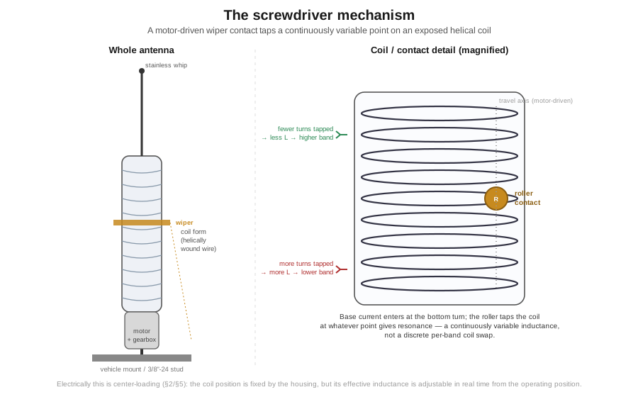
Electrically this is a center-loading design in the Vol 1 sense — the coil’s position on the mast is fixed by the housing, roughly midway up the assembly on most commercial designs, which the loading-position ranking already places above base-loading and below a top-mounted capacitive hat. That single fact is the entire efficiency case for a screwdriver over a ham-stick on a given band: moving the loading element up from the base recovers a genuine high-current run of wire below the coil, exactly as Figure 1’s center-loaded panel shows, and the reported result across the mobile-HF literature is a per-band efficiency improvement over an equivalent-length ham-stick — though it does not close the gap all the way to a top-hat design’s efficiency, and it does not change the fundamental R_rad ∝ (h_eff/λ)² collapse on the low bands: a 6 ft screwdriver whip resonated on 80 m is still a small fraction of a quarter-wave and still a single-digit-to-low-double-digit-percent-efficient radiator, just a somewhat better one than the equivalent ham-stick.
The genuine, uncontested selling point is band-agility: a screwdriver retunes across the whole HF range in seconds from the driver’s seat, with no stop, no wrench, and no roadside stick swap. A related, larger cousin is the “bugcatcher”-style coil (after the Texas Bug Catcher and its descendants) — a substantially larger-diameter, higher-turn-count coil, usually manually tapped rather than motor-driven, mounted at a fixed mast point. Because it is physically larger, it typically carries higher Q than a compact screwdriver coil, and a well-built bugcatcher is commonly reported to modestly outperform an equivalent screwdriver at the same loading position, at the cost of the screwdriver’s in-motion retuning convenience.
3.5.1 Mechanical and corrosion failure modes
A screwdriver’s continuously variable mechanism is also its principal reliability liability, and every failure mode traces to the same fact: the roller/wiper contact is a sliding electrical connection carrying real RF current, exposed to weather, vibration, and years of thermal cycling. Roller wear is the most common long-term-ownership complaint — the contact surface burnishes, pits, or oxidizes at the point it dwells most (typically the operator’s most-used band), producing an intermittent or noisy connection that shows up as an erratic SWR or a dead spot rather than a clean failure. Moisture ingress into the coil housing is the second major path — the exposed helix the roller needs physical access to is, by the same necessity, not fully sealed from rain and road spray, and standing water inside the housing both corrodes the windings and can flash over between adjacent turns at legal-limit power exactly as the fixed-vertical dive’s power-handling section describes for any high-inductance coil under reactive voltage stress. Motor and gear-train wear is the third, more mundane path — a small gearmotor driving a linkage through years of daily retuning eventually loses precision or fails, and because it is rarely separately serviceable on compact commercial designs, a worn motor is often a whole-antenna repair rather than a $20 part swap. None of this is a reason to avoid the category; it is the price of the mechanism’s flexibility, which is why the mobile-HF community treats periodic contact cleaning and a dielectric-grease seal at the housing joints as routine maintenance.
3.5.2 The price reality
Three brand names dominate the amateur screwdriver-antenna market, and their current status differs enough to state plainly rather than repeat older secondary-source pricing. Hi-Q Antennas (store.hiqantennas.com) currently lists the Hi-Q-5 (160–6 m, 1.5 kW SSB, 37.75″ excluding whip and cap hat) at $1,345, and a Hi-Q-6/160 variant at $1,545; an Hi-Q-4 (80–6 m, 33.5″) is also in the current lineup, though no confirmed live price for that model could be verified. Tarheel Antennas publishes a full current model range on its own site — from the Baby Tarheel (7–54 MHz, 200 W, 36″ whip) up through the Model 100A-HP (3.2–28 MHz, 1.5 kW PEP, 6′ whip) — but the site explicitly declines to post prices (“subject to change without notification”) and every dealer listing checked showed the popular models out of stock, so no current Tarheel price could be confirmed live; treat any figure quoted for the brand elsewhere as unverified. Scorpion Antennas, maker of the well-regarded SA-680 “Black Widow” (10–80 m, 39″ retracted / 57″ extended, last new list price around $1,045), has gone out of business with the owner’s retirement in early 2026 — the SA-680 is now secondary-market-only, changing hands around $650–750 on the ham classifieds and eBay. The honest summary for a mid-to-late-2026 shopper: budget the $1,300–1,600 range for a currently manufactured, confirmed-price screwdriver from Hi-Q, treat Tarheel as a dealer-quote-required unknown, and do not expect to buy a new Scorpion at any price.
3.6 Capacity hats — buying back efficiency
The fixed-vertical dive’s loading-position ranking puts a capacitive top hat at the head of the class for exactly the reason Figure 1’s third panel illustrates: a hat’s shunt capacitance to free space sustains current close to its base value nearly to the physical tip instead of letting it taper away, a direct, quantifiable win for h_eff and therefore for R_rad. The mobile-HF market sells this upgrade as a bolt-on accessory rather than a whole new antenna: DX Engineering’s Hot Rodz capacity-hat kits — the DXE-HR-1P, currently $124.99 — replace a Hustler-style resonator’s plain stainless whip tip with a machined aluminum hub carrying eighteen stainless-steel rods (six each at 6″, 12″, and 24″), letting the operator size the hat to whatever the resonator and mount geometry allows, with plastic safety tips on every rod end for the obvious reason that a car-wash attendant’s hand and a bare stainless spoke do not belong in the same universe.
Bolting a cap hat onto an existing base-loaded ham-stick or resonator does not turn it into a genuine top-loaded design — the coil is still at the base doing most of the reactance-cancelling work. What it does do, per the ranking’s own “hybrid” tier, is move the combination from the base-loaded 5–15% band toward the 30–50% band a top-hat-plus-small-coil hybrid achieves — a substantial gain for one accessory kit and the mechanical fuss of a larger, wind-loaded structure at the mast top. That wind load is the real tradeoff: a spoked hat several feet across at highway speed is a lever arm on the whip’s base and mount hardware a bare stainless tip never was, and hat manufacturers all caution about checking mount torque and joint integrity more often once one is added. For a fixed-mast, low-band-focused station running mostly 40 and 80 m, a cap hat is one of the better dollar-for-dB upgrades here; for a rig that lives at 70 mph, the added wind load and mechanical-failure risk are a real cost against the gain.
3.7 Backpack-portable HF — MP-1, AX-1, Buddistick/Buddipole, Wolf River Coil
The backpack-portable segment answers a different design brief than the vehicle-mobile family: there is no vehicle body to lean on for even a marginal ground reference, the whole station has to fit in a bag light enough to carry up a trail, and the antenna typically has to be assembled and torn down in minutes rather than left permanently mounted. All four antennas surveyed here share the same electrical strategy — a coil-loaded vertical, most of them tap-adjustable (a center-loading design the operator retunes by hand, moving a slider or tap point along the coil rather than swapping a part) — and all four ship, or explicitly recommend, a counterpoise wire that §8 argues is not an accessory but the other half of the antenna.
3.7.1 Super Antenna MP-1
The MP-1 line (Super Antenna Systems Corporation, current manufacturer site newsuperantenna.com) is the antenna most amateurs picture first when “portable HF vertical” comes up, in continuous production since the 1990s. The base MP1B/SuperStick configuration, per the manufacturer’s own current spec copy, covers 40 through 6 m plus 7–30 MHz continuous shortwave and 30–170 MHz VHF, extends to roughly 7 ft (2.13 m) tuned for 40 m, collapses to about 12″ (30 cm), and weighs approximately 1 lb (0.45 kg) bare; a tap-adjustable coil gives coarse band changes and the telescoping upper section gives fine trim. The MP1B was listed discontinued at the reseller checked, and no current live price for the bare antenna could be confirmed — the verifiable reference point is the MP1DXMAX full go-bag package (antenna, tripod, universal mount, dedicated 80/60 m coils, radial set, bag), currently $589.95 regular / $479.95 promotional through hamradio.com (sale through August 2026), extending coverage down to 80/75/60 m that the bare stick’s own sheet does not claim, rated 500 W SSB / 300 W CW-digital, and weighing about 6.5 lb (3.0 kg) complete. Efficiency figures of 25–50% on 40 m and 20–30% on 80 m circulate widely for this tap-adjustable center-loaded class — well above §3’s base-loaded ham-stick figures at the same bands, both because the center-loaded position outperforms base-loading per §5’s ranking and because these community figures typically assume the deployed-radial counterpoise §8 argues for, rather than the bare vehicle-body return a ham-stick’s own table assumes — but these are community estimates, not a manufacturer-published measured figure.
3.7.2 Elecraft AX-1
The AX-1 is the smallest antenna in this survey, and also the entry where the migrated seed material was simply wrong: that draft’s “17-ft whip” figure describes an antenna roughly four times too long. The manufacturer’s current specification page states the AX-1 extends to 45″ (115 cm) and collapses to 6″ (15 cm), weighs 3.2 oz (90 g) for the antenna plus 0.6 oz (17 g) for the included ground wire, and covers 20 m in one coil-selector position and a tunable range spanning 17/15 m in the other. Elecraft’s own spec copy adds a hedge worth keeping rather than flattening into a guarantee: a wide-range internal ATU such as the KX2/KX3’s “can often provide an adequate match on 12 and 10 meters as well” — a real, frequently-usable extension of the 17/15 m position’s range, but a conditional one, not a third dedicated coil position the way 20 m and 17/15 m are. Power rating is a genuinely QRP 30 W; price is $131.95 direct from elecraft.com, and it ships with a 13 ft (4.0 m) counterpoise wire pre-fitted with a lug. At under four ounces and folding to the size of a fountain pen, the AX-1 earns its SOTA/POTA reputation specifically because it does not pretend to cover 80 or 40 m — it is a purpose-built high-band QRP whip, not a compromise multiband design, and its honest efficiency on 20 and 17 m with a well-deployed counterpoise is respectable precisely because those bands sit far enough up §3’s fraction-of-quarter-wave curve that even a whip this short isn’t fighting an 80 m ham-stick’s uphill battle.
3.7.3 Buddistick / Buddipole
The Buddipole company’s parts-library approach — telescoping whip sections, a loading coil, mast sections, and counterpoise wires that snap together into either a vertical (the “Buddistick”) or a horizontal-dipole configuration (the “Buddipole”) — trades a higher parts count and longer setup time for genuine site-adaptable flexibility. The current Buddistick PRO, per the manufacturer’s product page, covers 40 through 6 m, weighs 2.5 lb (1.2 kg), collapses to 13″ (33 cm), extends to 8 ft (2.44 m), is rated 250 W PEP, and lists at $199, packaged in a Cordura bag with a “Versahub” feedpoint, two aluminum arms, a telescopic whip, an adjustable coil with three coil clips, and — the detail that matters most for §8 — an elevated radial system included in the base package rather than sold separately. That inclusion is a real point in the Buddistick’s favor: a counterpoise an operator has to remember to buy separately is a counterpoise some fraction of them will simply never own.
3.7.4 Wolf River Coils TIA
Wolf River Coils’ “Take It Anywhere” (TIA) line is the budget-tier version of the same coil-loaded-vertical concept, built around the company’s own Silver Bullet coil rather than a licensed or cloned MP-1 mechanism. The base SB 1000 TIA package — coil, three-legged aluminum tripod pod (legs roughly 12″ long, pod body about 6″ tall per independent user documentation), and an SO-239 coax connection — currently lists at $150 direct from wolfrivercoils.com, with a “Mega” variant (larger coil, broader low-band coverage) at $170 and a bare coil alone at $75; a counterpoise Radial Kit is sold separately for $20, and a collapsible whip runs a further $15–65 depending on length — worth flagging, since the TIA’s advertised low headline price omits the two components (whip, radials) that make it a working antenna, and a realistic complete-kit price runs closer to $220–250 once added. Power rating is modest and mode-dependent: up to 100 W SSB, 50 W CW, and 20 W on digital — a meaningfully lower digital figure than the flat “100 W” some older sources quote, sensible given how much less thermal headroom a 100%-duty-cycle digital signal leaves a small coil versus SSB’s natural relief between syllables. User-reported coverage with the appropriate whip runs 80 through 10 m, though the manufacturer’s copy does not itemize a per-band table the way Elecraft’s or Super Antenna’s do, so treat the low-band figures as community-reported rather than datasheet-confirmed.
Table 2 — 7.4 Wolf River Coils TIA
| Antenna | Bands | Collapsed / extended | Weight | Power | Price (as of late July 2026) |
|---|---|---|---|---|---|
| Super Antenna MP1DXMAX (full kit) | 80–6 m + shortwave/VHF | 12″ / 7 ft | 6.5 lb | 500 W SSB / 300 W CW-digital | $479.95–$589.95 |
| Elecraft AX-1 | 20 m, 17/15 m (+12/10 m w/ ATU) | 6″ / 45″ | 3.8 oz w/ ground wire | 30 W | $131.95 |
| Buddistick PRO | 40–6 m | 13″ / 8 ft | 2.5 lb | 250 W PEP | $199 |
| Wolf River SB 1000 TIA (coil + tripod only) | ~80–10 m (whip-dependent) | 6″ pod, 12″ legs | not published | 100 W SSB / 50 W CW / 20 W digital | $150 (+whip, +$20 radial kit) |
3.8 The counterpoise you must deploy
Every antenna surveyed in this volume — ham-stick, screwdriver, MP-1, AX-1, Buddistick, Wolf River Coil — is a monopole, and Vol 1 of the fixed-vertical dive establishes the structural fact a monopole never escapes: it is electrically half of a dipole, working against an image formed by whatever conducting reference sits below the feedpoint. A fixed-station vertical gets that reference from a radial field the companion volume on pattern and ground effect quantifies exhaustively — tens of buried radials, or as few as four properly elevated ones, engineered to hold the return-current loss resistance down near a few ohms. A vehicle-mobile ham-stick borrows a cruder version of the same idea from the vehicle’s own body and its capacitive coupling to earth, structurally worse than a fixed installation’s radial field. A backpack antenna gets nothing unless the operator deploys one — the single most common mistake in portable HF, common enough to deserve the blunt framing this section opens with: for a portable vertical, the counterpoise is not an accessory. It is half the antenna, and skipping it does not make the antenna not work — it makes the antenna’s return path your own body and the dirt under your boots.
3.8.1 Why a good SWR without the counterpoise is a lie
The mechanism is exactly the η = R_rad / (R_rad + R_loss) bookkeeping the fixed-vertical dive’s radial-field volume builds from scratch, applied to a case where R_loss is unusually large and largely invisible from the operating position. A resonant, well-matched antenna presents something close to 50 Ω resistive at its feedpoint regardless of where that resistance physically comes from — the SWR meter cannot distinguish “36 Ω of genuine radiation resistance plus 14 Ω of well-designed matching-network resistance” from “8 Ω of radiation resistance plus 42 Ω of the operator’s own body and the damp soil beneath their boots doing the job a counterpoise should be doing.” Both cases tune to a comfortable 1.3:1 or better and both happily accept 100 W. The difference is entirely in how that power gets spent, and a low SWR is silent on that question by construction — it measures reactance cancellation and resistance match at one point in the circuit, not the destination of the real power that flows once the match is achieved. Figure 4 makes this concrete across three deployment choices for the identical antenna, all reading essentially the same SWR, with a 5–10 dB efficiency spread hiding entirely behind that shared number.
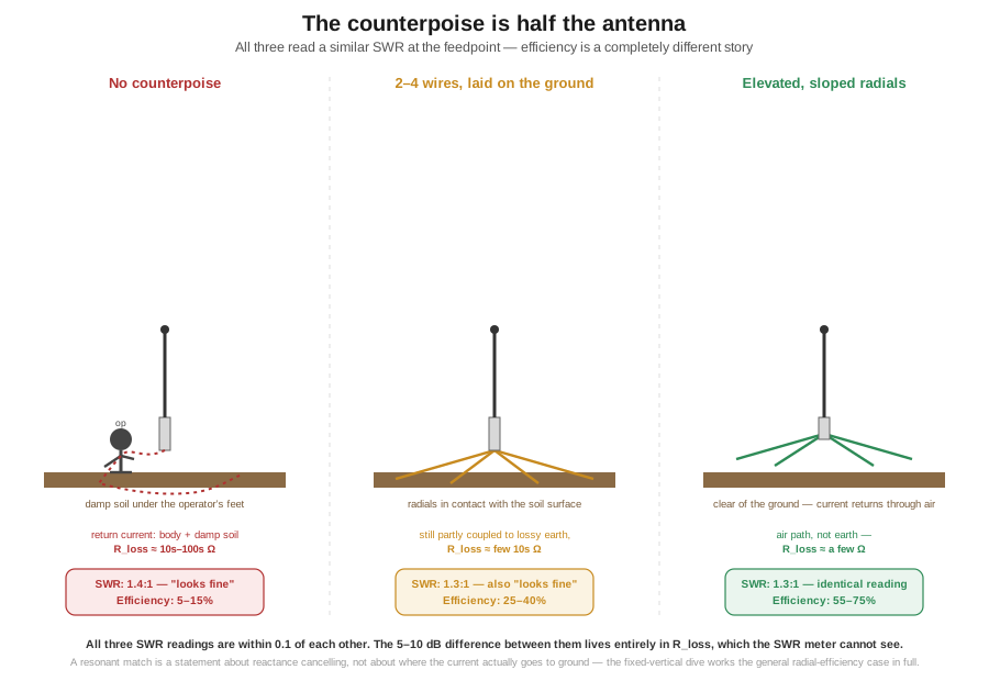
This is the single most consequential idea a new portable-HF operator needs to internalize, and it is worth restating in its most operational form: a “great SWR, first try” result on a bare portable vertical with no counterpoise deployed is not a sign the antenna is working well. It is very often a sign the antenna is quietly dumping most of your transmitter’s power into your own legs and the ground under your feet, and the matching network — or the antenna’s own reactance — has simply absorbed the reflection that would otherwise have warned you. The fix costs one to three minutes of setup time and, per the manufacturer’s own deployment instructions across every antenna in §7, is not optional equipment — it is the return half of the circuit.
3.8.2 How many wires, how long, on the ground or elevated
The fixed-vertical dive’s radial-field volume works out why a large buried radial field needs dozens of wires (each only a partial, lossy solution to an earth-conduction problem, with diminishing returns past 32–60) while an elevated system needs as few as four (enough for genuine rotational symmetry, current returning through low-loss air). Portable HF sits in an instructive middle ground, and the honest answer for “how many, how long, on the ground or up in the air” depends on which of the three regimes in Figure 4 the deployment lands in.
No counterpoise at all is the worst case by a wide margin and is, unfortunately, the default outcome of an operator who trusts the SWR meter and stops there — §8.1’s whole argument. A single wire laid on the ground, what a rushed setup often produces, is a real improvement over nothing but still couples substantially into the lossy earth it lies against, because a bare wire in contact with damp soil is itself a lossy, ground-referenced structure rather than a clean return path. Two to four wires laid outward from the base, the configuration the MP-1 community and the ARRL’s own portable-operating guidance commonly recommend, spreads the return current across more paths and buys back a meaningful fraction of the gap — moving a typical setup from the single-digit-percent regime toward the 25–40% range §7 cites for a properly counterpoised MP-1-class vertical on 40 m. Properly elevated, sloped radials clear of the ground — the same technique Vol 2 of the fixed-vertical dive develops, scaled to portable dimensions — is the best option when site and mount allow it, because it alone routes return current through air rather than earth; a wire sloped down and away from a mast-mounted feedpoint, kept clear of the actual ground, behaves close to the resonant-radial case that volume quantifies at under 0.3 dB of loss, rather than the several-dB loss a ground-contact wire still carries.
Length matters, though less than deployment geometry does. A resonant counterpoise — cut to a quarter-wave at the operating frequency — presents the cleanest, lowest-impedance return path and is worth doing for a single-band antenna or an operator willing to carry a per-band set of wires. Several antennas in §7 instead ship one fixed-length counterpoise used across every band — the AX-1’s 13 ft wire is the clearest example, serving both its 20 m and 17/15 m positions without being individually resonant at either — a sensible compromise given the antenna’s tiny size budget: most of the benefit comes from getting any return conductor up off the lossy earth at all, with the resonant-length refinement adding a smaller improvement on top rather than being the dominant factor. The practical rule: deploy at least one counterpoise wire every time, get it up off the ground if the site allows it, and treat exact length as a second-order refinement, not a reason to skip deployment for want of the “right” length.
3.9 Where this volume hands off
This volume took Vol 1’s loading physics into the hardware an actual mobile or backpack HF operator carries: the ham-stick’s base-loaded, one-stick-per-band geometry and the Hustler mast-and-resonator system that packages the same idea with a faster swap; a single, honestly reconciled efficiency-by-band table replacing the two disagreeing tables the seed material carried, with every assumption stated rather than hidden; the reason loading-coil Q dominates the low-band story and why it matters far less on 15 and 10 m; the screwdriver’s continuously variable center-loaded mechanism, its per-band efficiency edge over a ham-stick, its real mechanical and corrosion failure modes, and a price reality that now includes one major manufacturer (Scorpion) gone out of business entirely; the capacity hat as a genuine bolt-on efficiency upgrade with the wind-load cost that comes with it; and the backpack-portable survey (MP-1, AX-1, Buddistick/Buddipole, Wolf River Coil) with every length, weight, band, and price claim checked against a live vendor page — including the AX-1’s true 45″ extended length in place of the migrated draft’s mistaken “17-ft whip.” It closed on the argument the whole volume built toward: a portable vertical’s counterpoise is not an accessory, a satisfying SWR reading with none deployed is actively misleading rather than reassuring, and the real fix costs a few minutes and a handful of wire, not a better antenna.
What this volume does not cover is the loading-theory derivation itself — Vol 1’s subject, applied here rather than re-derived — or the vehicle-roof VHF/UHF mag-mount and NMO family, the J-pole/Slim-Jim deploy-and-go antennas, the rubber-duck-and-helical handheld family, or the SDR-receive telescoping-whip case, all of which belong to companion volumes elsewhere in this dive. For the fixed-station version of everything this volume’s counterpoise section leans on — the full buried-versus-elevated radial-field argument and the loading-position ranking applied here to a mobile whip rather than derived from scratch — the fixed-vertical-monopoles dive is the primary source and the right place to go next.
3.10 Resources
- ARRL Antenna Book (25th+ ed.), the mobile and portable operations chapter — the canonical treatment of mobile-HF loading and the general shortened-vertical efficiency guidance this volume’s §3–4 apply to a specific geometry.
- W8JI (Tom Rauch), “Mobile Antennas, Short Verticals, Loading Coil Loss, and Loading Coil Current” (w8ji.com) — the worked coil-Q-versus-ground-loss numerical example §4 cites directly.
- DX Engineering (dxengineering.com) — current Hustler resonator, mast, and Hot Rodz capacity-hat pricing verified for this volume as of late July 2026.
- Elecraft (elecraft.com) — the AX-1 manufacturer specification page, the primary source correcting this dive’s earlier “17-ft whip” error.
- Super Antenna Systems Corporation (newsuperantenna.com) and hamradio.com — MP-1/MP1DXMAX manufacturer and dealer specification and pricing sources.
- Buddipole, Inc. (buddipole.com) — Buddistick PRO current specification and pricing.
- Wolf River Coils (wolfrivercoils.com) — TIA and Silver Bullet current product and pricing.
- Hi-Q Antennas (store.hiqantennas.com) and Tarheel Antennas (tarheelantennas.com) — current screwdriver-antenna model lineups; Hi-Q pricing confirmed live, Tarheel pricing not publicly posted at the time of writing.
- Vol 1 of this dive — the loading-position physics, the
R_rad ∝ (h_eff/λ)²derivation, and the Chu-Harrington bound this volume applies throughout. - The fixed-vertical-monopoles dive, especially Vol 2 (pattern, ground effect and the radial field) and Vol 4 (shortened & loaded verticals) — this volume’s closest technical sibling and the source for the general loading-position ranking and radial-efficiency framework §3, §4, and §8 apply to the mobile/portable case.
Comments (0)