Portable & Mobile Monopoles · Volume 2
Vehicle-Mobile — The Roof as Ground Plane
Electrical roof size band by band, mount position and its pattern cost, NMO/mag-mount/lip/3/8-24 hardware, coax and common-mode in a metal box, the VHF/UHF collinear whip catalogue, why mobile HF is the hard case, and the noise floor that usually sets the real limit
2.1 About this volume
Vol 1 framed the portable-monopole problem in general terms: every antenna in this dive gives something up to fit the operator’s constraints, and the defining variable is what counterpoise the installation actually has — the operator’s own body for a handheld, a vehicle roof for a mobile rig, or nothing at all. This volume takes the second case and works it properly. A vehicle roof is, at VHF and UHF, the closest thing a mobile installation has to the textbook “infinite ground plane” the image-plane derivation in the fixed-vertical dive assumes — which is exactly why a competently mounted 2 m/70 cm mobile whip routinely outperforms a handheld with an aftermarket antenna by 10–20 dB, most of that gap coming from the ground reference rather than from the whip itself — though a stock handheld antenna’s own mismatch and resistive loss contribute their share too, independent of any counterpoise question. That advantage is band-dependent in a way worth taking seriously rather than asserting: the same physical roof is a wildly different electrical structure at 50 MHz than it is at 446 MHz, and this volume’s first job (§2) is to make that difference quantitative rather than hand-waved.
From there the volume works outward through everything that determines how much of the roof’s potential a real installation actually captures: where you put the hole (§3), what hardware goes in it and why NMO won the mount war (§4), how the coax gets from the roof to the radio without becoming its own noise antenna in a metal box (§5), and the actual VHF/UHF product catalogue of collinear and phased whips that convert a good image plane into real dB of gain (§6–7). Section 8 states — but does not solve — the reason mobile HF is a structurally different and harder problem: the same roof that is several wavelengths at 446 MHz is a fraction of a percent of a wavelength at 3.65 MHz, and no amount of mount-position cleverness fixes that. The loaded whips, ham-sticks, and screwdriver antennas that make mobile HF work anyway are Vol 3’s subject, not this one’s. Section 9 closes on an observation every experienced mobile operator learns the hard way: a vehicle is an unusually noisy place to put a receiver, and past a certain point in the antenna’s own quality, the noise floor generated a few feet from the whip — not the whip’s gain figure — is what actually limits how well the station hears.
This volume does not re-derive the radial-field efficiency formalism, the pseudo-Brewster ground degradation, or the buried-vs-elevated radial tradeoff — those live in full in the fixed-vertical dive’s Vol 1–2, and a vehicle roof is a genuinely different structure from a buried or elevated radial field (a solid conductive sheet rather than a sparse wire fan), so the two treatments are complementary rather than duplicative. Where the roof’s behavior reduces to the same underlying physics — a finite conductor standing in for an ideal infinite ground plane — this volume cites that treatment rather than re-deriving it.
2.2 The roof as an image plane — electrical size band by band
Image-plane theory says a monopole over an infinite, perfectly conducting ground radiates exactly the upper half of a dipole’s pattern, with a resonant feedpoint resistance of roughly 36 Ω — half the dipole’s 73 Ω, because half the structure is a mirror image rather than a physical conductor. Every quarter-wave (and 5/8-wave, and collinear) mobile whip on the market is implicitly leaning on that assumption, and the assumption is only as good as the “infinite” part. A vehicle roof is a finite, oddly shaped conductor with a windshield-sized hole in one end and a trunk-sized step-down in the other, and how well it approximates the ideal image plane is entirely a question of its size in wavelengths at the operating frequency — not its size in inches, which never changes.
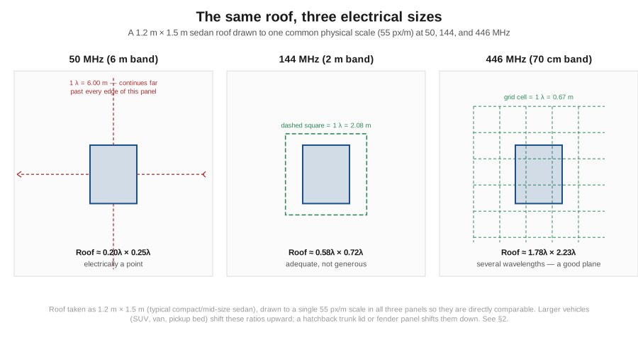
Take a representative compact-to-mid-size sedan roof as roughly 1.2 m wide by 1.5 m long (fore-aft) — a reasonable planning figure, though a full-size SUV, a van, or a pickup cab roof will run larger, and a hatchback trunk lid or a fender panel considerably smaller, all of which matters directly for §3. At three representative amateur VHF/UHF design frequencies, the free-space wavelength λ = 300/f_MHz gives:
Table 1 — Take a representative compact-to-mid-size sedan roof as roughly 1.2 m wide by 1.5 m long (fore-aft) — a reasonable planning figure, though a full-size SUV, a van, or a pickup cab roof will run larger, and a hatchback trunk lid or a fender panel considerably smaller, all of which matters directly for §3. At three representative amateur VHF/UHF design frequencies, the free-space wavelength λ = 300/fMHz gives
| Design freq | λ | Roof width in λ | Roof length in λ | Roof area in λ² |
|---|---|---|---|---|
| 50 MHz (6 m) | 6.000 m | 0.200λ | 0.250λ | ≈0.050 λ² |
| 144 MHz (2 m) | 2.083 m | 0.576λ | 0.720λ | ≈0.415 λ² |
| 446 MHz (70 cm) | 0.6726 m | 1.784λ | 2.230λ | ≈3.980 λ² |
The spread is the whole story: the identical physical roof runs from a twentieth of a square wavelength at 6 m to nearly four square wavelengths at 70 cm — roughly an 80-fold change in electrical area across a factor of only 9 in frequency, because area scales with the square of the linear electrical dimension. At 50 MHz the roof is, for image-plane purposes, barely bigger than a point; a 6 m mobile whip is not really operating “over a ground plane” in the sense the fixed-vertical dive means it, and the antenna’s actual feedpoint impedance, pattern, and efficiency all depend more on the specific vehicle’s body shape, the tires’ capacitive coupling to the road, and the physical proximity of the engine block and frame than on any clean image-plane number. At 144 MHz the roof crosses into “adequate but not generous” — 0.576λ × 0.720λ is large enough that the image-plane approximation starts to hold reasonably well, feedpoint impedance and pattern both become fairly predictable and repeatable across similar vehicles, but the plane is still small enough that mount position (§3) and the specific vehicle’s proportions still move the numbers by a dB or so. At 446 MHz the roof is a genuinely large image plane — 1.78λ × 2.23λ is comfortably into the region where a real quarter-wave or 5/8-wave whip behaves close to its idealized-infinite-ground-plane spec sheet number, which is a large part of why 70 cm mobile gain figures in the catalogue (§6–7) run measurably higher than the same physical whip’s 2 m figure on the identical roof.
The practical upshot for a builder reading a Smith chart or an SWR sweep off a NanoVNA is this: don’t expect the same whip to show the same feedpoint behavior on 6 m that it shows on 70 cm, even discounting the element’s own frequency response, because the ground reference itself is a different electrical object at each frequency. A 6 m mobile installation that shows a squirrelly, position-sensitive SWR curve that shifts noticeably when you move the antenna six inches fore-or-aft on the roof is not a defective antenna — it is an electrically-point-sized image plane doing exactly what an electrically-point-sized image plane does. A 70 cm installation showing a stable, repeatable, near-textbook SWR curve regardless of exactly where on the roof you put the NMO hole is the same physics running the other direction.
2.3 Mount position and its pattern cost
Given a roof that is at least a reasonably competent image plane (144 MHz and up, per §2), where on that roof the whip sits is the next variable, and it is not a cosmetic one. Image-plane theory’s clean omnidirectional-in-azimuth prediction assumes the conductor is symmetric around the feedpoint in every direction — the same assumption the fixed-vertical dive’s §4 makes about a buried or elevated radial field, and the same failure mode applies when that symmetry is broken: an asymmetric ground reference squints and distorts the azimuth pattern rather than destroying it outright.
Roof-center is the textbook position for exactly this reason — a whip mounted at the geometric center of the roof sees a roughly comparable run of sheet metal in every direction (forward across the roof and hood, aft across the roof and trunk lid, and to both sides down the door panels), which is as close as a passenger vehicle gets to the rotationally symmetric image plane the theory assumes. It is also, not coincidentally, usually the position with the most metal within a wavelength or so in every direction, which per §2 matters more at 144 MHz than at 446 MHz.
Trunk mount (a common NMO or lip-mount position on sedans, chosen for looks and because it doesn’t put a hole through the visible roof skin) breaks that symmetry in a specific and predictable way: looking forward, the whip still sees the roof and the hood — a comparable run of conductor to the roof-center case. Looking aft, it sees only the trunk lid, which is both shorter and often more sharply stepped-down than the roof-to-hood transition forward. The image plane is now asymmetric front-to-back, and the elevation pattern responds by tilting and compressing on the short side — the low-angle lobe that a competent image plane would hold near the horizon lifts and weakens looking aft, while the forward-looking direction stays closer to the roof-center ideal. Fender mount and hatch-lip mount push the same effect further: a fender sits low, close to a nearly-vertical body panel and the wheel well, with the image plane essentially reduced to whatever sheet metal is within a few tens of centimeters, and a hatchback’s hatch lip is thin, often only tenuously bonded to the rest of the body shell through hinges and weatherstripping rather than a continuous conductive sheet.
Honest numbers here deserve a caveat before the figure: this is a modeling result for the mechanism, not a measured trace for any specific vehicle, and it should be read that way. The pattern below shows an illustrative elevation cross-section for a roof-center mount against a trunk-lid NMO looking forward (over the hood) and aft (over the lid), each referenced to its own peak:
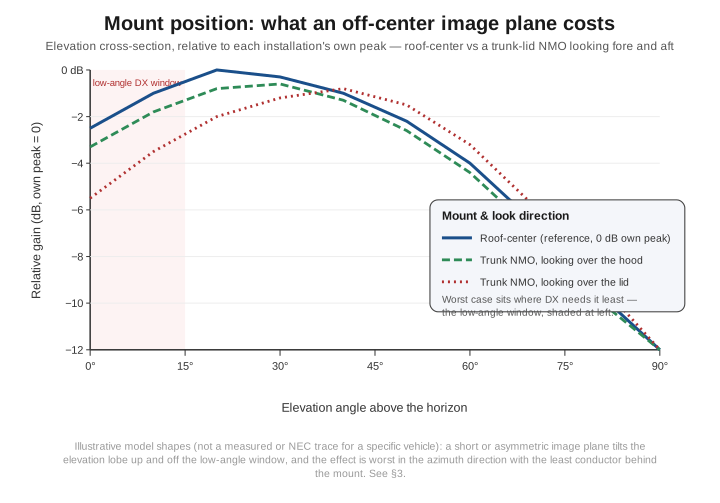
The shape the model predicts — and that the honest, hedged literature on the subject broadly agrees with — is a 0.5–2 dB loss in the favorable look direction from a trunk or fender mount relative to roof-center, growing to something more like 2–5 dB in the unfavorable direction (looking aft off a trunk mount, or in the direction a fender mount’s own body bulk shadows), with the loss concentrated disproportionately at the low elevation angles that matter most for VHF/UHF simplex and weak-signal work. That last point is the one worth internalizing rather than the specific numbers: the mount-position penalty is worst exactly where the antenna’s gain matters most. A trunk-mounted whip is not “a couple dB worse everywhere” — it is close to full performance driving toward a repeater ahead of you and measurably worse driving away from it, which is a real and directionally-asymmetric effect rather than a flat derate.
One more honest note belongs here: several of the commercial whips in §6–7 (the Comet SBB-5 and the Diamond NR770HNMO both among them) are marketed with language like “radialless design” or “does not require ground plane.” That claim is not fantasy, but it is also not a free pass around everything in §2–3. These designs are understood to use an internal matching network — typically a form of shunt feed or a sleeve/skirt arrangement along the lower part of the radiator that establishes a local counterpoise reference on the antenna itself rather than depending entirely on the mounting surface — which measurably improves tolerance to poor or absent ground planes (a fiberglass cab roof, a small metal patch, a non-conductive mount) at some cost in idealized peak gain relative to what the same physical structure would do over a genuinely large, conductive roof. Treat “radialless” as “more forgiving of a bad image plane,” not as “the image plane doesn’t matter” — everything in §2 about roof size still applies; these designs simply fall off that cliff more gently.
2.4 Mount hardware — NMO, mag-mount, lip, 3/8-24, and PL-259/SO-239 chassis
NMO is the de-facto standard for permanent VHF/UHF mobile installation, and it is worth knowing where the name comes from because the history explains the mechanical design. NMO is widely credited to Motorola — “New Motorola Mount” is the conventional expansion, dating from commercial land-mobile work; sources differ on whether that happened in the 1960s or the 1970s, and this volume won’t pretend to more precision on the date than the record actually supports. What matters mechanically has stayed constant since: a 3/4-inch hole through the roof skin, a threaded cup mounted beneath it with a spring-loaded coax pin, a rubber gasket sealing the hole, and a bayonet-and-spring mechanical interface that lets any NMO-compatible whip be twisted in or out in seconds without tools. That last property — quick, tool-free antenna swaps on a mount that is otherwise a permanent, weatherproofed, drilled installation — is the actual reason NMO won over its competitors: a fleet vehicle or a multi-band ham station can carry a 2 m whip, a 70 cm whip, and a dual-band whip and swap between them at will, all through the same hole.
On frequency range, the honest answer is a range rather than a single crisp number, because published NMO specifications are not standardized to one datasheet. A generic connector-catalogue NMO mount is commonly rated broadband to several GHz for pure connector continuity (Pasternack’s catalog NMO mount part, for instance, is specified to 5 GHz); purpose-built HF-capable NMO variants such as Larsen’s NMOHF line are specified down to 27 MHz for the low end, extending up past 6 GHz. Treat “DC to several GHz” as the honest summary rather than quoting one manufacturer’s number as if it were “the” NMO spec — the mount itself is a broadband coaxial interface, but which whip you thread into it, not the mount, is almost always the actual frequency-limiting element in a real installation.
Because a through-hole NMO installation is permanent and goes through paint and clear-coat, the bonding detail matters in a way that’s easy to skip past: the mount’s base flange needs a genuine metal-to-metal DC bond to the vehicle body, not just a gasket sitting on top of clear-coat, or the joint becomes an intermittent, corrosion-prone, weather-sensitive contact that can add resistive noise and unpredictable SWR over the years rather than the day it was installed. Serrated star washers or scraping a bare-metal ring around the hole under the mount’s flange are the standard fix. Vibration shows up in two failure modes worth naming: the coax pin inside the mount’s spring contact can loosen over years of highway vibration into an intermittent short or open, showing up as a maddeningly intermittent SWR or dead-key fault that only appears over bumps; and the whip itself, especially a tall, thin stainless “Kulrod” element flexing continuously at highway speed, is a genuine metal-fatigue problem at the base — the reason several of the catalogue entries in §6–7 specifically advertise a fold-over hinge feature, which lets the whip lay down for a car wash or a low garage rather than absorbing that flex at the one point (the base) where fatigue failure actually happens.
Magnetic mounts solve the “no permanent hole” problem, and understanding why they work is more interesting than the marketing copy suggests, because a mag-mount is emphatically not a DC ground connection. The magnet sits on top of a thin rubber or felt protective boot, which sits on top of the vehicle’s clear-coat and paint, which sits on top of the actual conductive sheet metal — there is no continuous metallic path from the antenna’s ground reference to the car body at all. What actually happens is capacitive coupling: the magnet’s steel body and the vehicle’s sheet metal form the two plates of a capacitor, with the paint, clear-coat, and boot material acting as the dielectric between them. At RF that capacitive reactance, X_C = 1/(2πfC), is what stands in for a hard ground bond, and the entire reason mag-mounts work acceptably at VHF/UHF and progressively worse at lower frequencies is that X_C scales inversely with frequency — the same physical capacitor presents a much lower, more tolerable series reactance at 446 MHz than it does at, say, 27 MHz, where that same reactance becomes large enough to meaningfully detune the antenna and add loss. This volume won’t put a specific picofarad number on that capacitor — the actual value depends on magnet contact area, boot thickness, and paint/clear-coat thickness in ways no single citable source nails down generally — but the scaling argument is solid, standard RF engineering, and it is exactly why HF mag-mount installations (§8, and developed properly in Vol 3) need an explicit bonding strap or a deployed counterpoise wire rather than relying on the magnet’s own capacitive coupling the way a 2 m or 70 cm mag-mount whip reasonably can. Two purely mechanical cautions round this out: a mag-mount left in place for hours in summer sun can leave a paint-damaging heat/pressure ring, and the magnet-to-paint interface picks up grit that scratches the clear-coat over repeated placements — a felt pad and a clean mounting surface are cheap insurance against both.
Lip mounts — the trunk-lid or hatch-lid clip mount, requiring no hole and no magnet — trade both of those installations’ advantages for a genuinely weaker mechanical and electrical connection: the clamp grips a thin, often already-flexing sheet-metal lip, the ground bond depends on a small serrated contact area biting through paint at the clamp jaws, and the cantilever load of a tall whip puts real bending stress concentrated at that one thin, poorly-supported edge. Lip mounts are consistently rated for lower power than an equivalent NMO or mag-mount installation, and it shows up as a durability problem before it shows up as an RF problem — the clamp loosening, the paint at the contact point corroding, or the lip itself fatiguing under repeated flex.
3/8″-24 threaded studs predate NMO in mobile service and remain the standard for hardware NMO’s own spring-pin mechanism isn’t built to carry: a full-length HF ham-stick or a screwdriver antenna’s motor housing is heavier and imposes far more cantilever leverage on its mount than a compact VHF/UHF whip does, and a 3/8″-24 stud threaded directly into a heavy-duty ball mount or a reinforced trunk-lip bracket handles that load in a way NMO’s quick-swap bayonet mechanism was never designed for. This is why the HF mobile whip catalogue Vol 3 covers still commonly specifies a 3/8″-24 mount rather than NMO, even on vehicles that use NMO for their VHF/UHF whips.
SO-239/PL-259 chassis mounts — the UHF connector series bolted through a hand-fabricated bracket, or built into a whip’s own base the way several of the catalogue entries in §6–7 offer as an alternative to NMO — are bulkier and mechanically simpler than a threaded mount, but carry the UHF connector’s own well-known frequency ceiling: the PL-259/SO-239 pair is not an impedance-controlled connector geometry, and its loss and mismatch both climb noticeably as frequency rises, becoming a real concern well before 1 GHz. For 2 m and 70 cm mobile use that ceiling is rarely the binding constraint; it becomes one the moment an installation reaches into the microwave amateur bands or GPS/cellular frequencies, where BNC, TNC, or N-type hardware is the correct choice instead.
2.5 Coax, feedline choice, and common-mode in a metal box
Most of the mobile whips in §6–7 ship with a fixed length of coax already terminated — commonly RG-58, a thin, flexible 50 Ω cable that routes easily through a door seal grommet or an existing wiring pass-through without the drilling or fishing a stiffer cable demands. For the short runs a mobile installation actually needs — a roof-to-dash run is rarely more than 3–5 m — RG-58’s higher loss-per-foot compared to a fatter cable is a real number but rarely a decisive one at typical mobile transmit powers and typical run lengths; it becomes worth upgrading to something like LMR-240 or RG-8X specifically when a run is unusually long (a remote trunk-mounted radio with a long cable back to a dash-mounted head unit or control head), when the whip is being driven at the top of its rated power for extended keydown periods (digital modes, APRS beacon duty), or simply when the extra loss budget matters for a marginal weak-signal path. Route coax away from door hinges and pinch points, away from routing it in tight parallel runs alongside the vehicle’s own ignition and alternator wiring harness (§9 explains why that proximity specifically matters), and bond the shield to a single, well-defined ground point near the radio rather than letting it float or ground at multiple points, which is the standard prescription against ground loops in any installation, mobile or fixed.
The common-mode question is genuinely different in a vehicle than in a fixed shack, and it’s worth being precise about why. A house-based HF station worries about common-mode current on the feedline because the feedline runs through open space between a well-defined antenna and a well-defined shack, and any imbalance drives current onto the outside of the coax shield, which then re-radiates near the operating position. A vehicle is, for RF purposes, closer to a literal Faraday cage with one deliberate hole in it — the point where the coax transitions from the roof-mounted, chassis-bonded antenna feedpoint down through the headliner into the passenger compartment. At an NMO mount, the coax shield is already solidly bonded to the vehicle body right at the antenna’s own feedpoint, which is a genuinely better starting position than most fixed-station feedline-to-ground-system transitions get — the return current has a low-impedance path back to the same conductor the whole time. That single bonding point is why VHF/UHF mobile installations are, in practice, rarely troubled by common-mode symptoms the way a fixed HF station can be: the antenna’s own local ground is solid, the run is short, and the operating frequency is high enough that a few turns of coax through a clamp-on ferrite core (mix 43 material is the conventional VHF/UHF choice, per the same ferrite-mix guidance the single-band-dipole feedpoint-and-matching volume develops for a fixed dipole’s balun) chokes off what little common-mode current does develop.
Where this genuinely changes is at HF (§8, and properly Vol 3’s subject): a mobile HF installation’s “ground” is the vehicle body’s diffuse, largely capacitive coupling to actual earth rather than a solid local bond, the antenna itself is usually a loaded, high-Q, narrowband structure sensitive to exactly the kind of reactive perturbation a poorly choked feedline introduces, and the symptoms that show up — RF feedback into a microphone, distorted receive audio, erratic SWR readings that shift when the operator’s hand moves near the mic cable — are the same common-mode pathology a fixed shack fights, just compressed into a smaller, more electrically crowded space. A mix-31 clamp-on choke (the material generally favored for HF common-mode suppression) near the point where the coax leaves the trunk or the roof mount into the cabin is cheap, effective insurance, and worth building into any HF-capable mobile installation as a matter of course rather than a troubleshooting afterthought.
2.6 The VHF/UHF whip catalogue — collinear and phased designs
A plain quarter-wave whip over a good image plane is the reference point the fixed-vertical dive already quantifies at 5.15 dBi over an ideal infinite ground — real mobile whips exist to beat that number, and they do it with one of a small number of related tricks rather than sheer physical length.
The 5/8-wave whip is the simplest of these and the right place to build intuition. A 5/8-wave element is longer than a resonant quarter-wave, which shifts where the current standing wave’s maximum sits: rather than the current maximum riding at the base (as it does for a quarter-wave fed directly at a current antinode), a 5/8-wave element’s current distribution has its global maximum roughly 60% of the way up the element, with a genuine current node — a point where the standing-wave current passes through zero — about 20% of the way up from the base, and a smaller, phase-reversed lobe below that node back down to the feed. That node is the whole reason a 5/8-wave whip needs a base-loading or phasing coil rather than a direct 50 Ω tap: the raw feedpoint impedance sitting right at (or just below) a current node is reactive and awkward to match, and the coil’s job is specifically to absorb that reactance and present something closer to 50 Ω resistive, while simultaneously correcting the phase relationship between the two lobes so they add constructively rather than partially canceling in the far field:
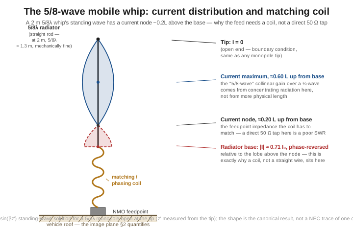
The payoff for carrying that coil is real: concentrating the current maximum higher up the element, closer to broadside, is conventionally credited with roughly 3 dB of gain over a plain quarter-wave in mobile service. It is worth being explicit about what that increment is measured from, because the reference is the part everyone drops. Mobile-whip gain figures are conventionally quoted against a real-world “unity gain” quarter-wave commercial whip — 0 dBd, i.e. about 2.15 dBi — not against the 5.15 dBi figure a quarter-wave achieves over a theoretically perfect infinite ground plane. Add the 5/8-wave’s ~3 dB to that 2.15 dBi baseline and you land near 5.15 dBi, which is precisely where a single-band 5/8-wave commercial whip like the Larsen NMO150B in §7 gets specified (5.1 dBi). The numerical coincidence between “quarter-wave over perfect ground” and “5/8-wave over a real vehicle” is exactly that — a coincidence of two different measurements landing on similar numbers — and conflating them is a common way to talk yourself into believing a mobile whip has 3 dB it does not have. At 2 m, a 5/8-wave element is about 1.3 m — long enough to be a straight rod rather than requiring any folding, which is exactly the mechanical form the Larsen product takes.
The dual-band collinear/phased whips that dominate the catalogue (the Comet SBB-5, the Diamond NR770HNMO, the Comet CA-2x4SR) push the same idea further by stacking multiple radiating sections, separated by phasing networks, so that several current maxima along the physical length add in phase rather than just one. This is also the answer to a pattern every dual-band whip’s spec sheet shows and that’s worth understanding rather than just reading off a table: the same physical whip is consistently specified at a noticeably higher gain on 70 cm than on 2 m — the Comet SBB-5 at roughly 3.0 dBi on 2 m against 5.5 dBi on 70 cm is typical. The reason is straightforward once you think of it in wavelengths rather than inches: the identical physical length that holds perhaps one or one-and-a-half effective radiating sections at 2 m’s longer wavelength holds three or four at 70 cm’s much shorter one, and each additional in-phase section is, in effect, another element in a phased collinear array — more elements, more gain, exactly the same mechanism a longer Yagi boom buys more gain from more directors. Some dual-band designs implement the frequency-selective part of this with a network that behaves loosely like a trap — presenting one electrical structure to the 2 m current and a functionally different, higher-order collinear structure to the 70 cm current on the same physical rod — though this volume won’t assert a specific manufacturer’s internal topology as verified fact; it’s a reasonable and commonly cited description of how these designs are understood to work, not a confirmed schematic for any one product.
One honesty note belongs here explicitly, because it’s the single most common way a mobile-whip gain claim misleads a careful reader: every gain figure in §7’s table is quoted relative to an idealized ground plane, almost always the manufacturer’s own anechoic or simulated infinite-ground-plane test setup, not the real roof it will actually sit on. Per §2–3, a real installation on a real, finite, possibly off-center roof will not fully realize the printed dBi number in every direction — treat the catalogue figures as a valid basis for comparing whips to each other under a consistent test condition, not as a guaranteed absolute performance number for your specific vehicle and mount position.
2.7 Workhorse whips — a verified buying table
Every model, gain figure, length, and price below was checked against a live vendor page or manufacturer datasheet in late July 2026, not carried forward from any earlier reference list. Several genuinely disagree with numbers that have circulated informally in older summaries of this market — those discrepancies are called out explicitly rather than quietly corrected, because a reader comparing this table against something else should know why the numbers moved.
Table 2 — 7. Workhorse whips — a verified buying table
| Whip | Bands | Gain (2 m / 70 cm) | Length | Mount | Power | Price (late Jul 2026) | Notes |
|---|---|---|---|---|---|---|---|
| Tram 1185 | 2 m/70 cm | unity / ~4.6 dBi (2.5 dBd) | 19 in | Mag-mount, incl. 12 ft RG-58 + PL-259 | 100 W | $32.99 (Walmart) | Budget, pretuned kit — antenna, mount, and cable in one box |
| MFJ-1729 | 2 m/70 cm | 2.6 / 6.3 dBi | 27.5 in | Mag-mount, incl. 12 ft coax + PL-259 | 300 W PEP | $49.95 (MFJ Enterprises, direct) | “PowerGain” SlimLine radiator; includes a BNC handheld adapter |
| Diamond NR770HNMO | 2 m/70 cm | ≈3.0 / 5.5 dBi (retailer-consensus; not stated on the manufacturer’s own listing — see note) | 38.2 in | NMO | 200 W | $55.99 (DX Engineering) | Marketed “radialless” / no-ground-plane-required — see §3 |
| Comet SBB-5 | 2 m/70 cm | 3.0 / 5.5 dBi | 38 in | NMO or PL-259 version | 120–200 W (listings vary — see note) | $62.95 (R&L Electronics) | The canonical mid-tier collinear; fold-over hinge |
| Comet CA-2x4SR | 2 m/70 cm | 3.8 / 6.2 dBi | 40 in | NMO or PL-259 version | 150 W (manufacturer spec, cometantenna.com; the Amazon listing states 200 W) | $71.95 (R&L Electronics) | Step up in gain from the SBB-5; broader SWR bandwidth |
| Larsen NMO150B | 2 m only | 5.1 dBi (5/8-wave) | 51.5 in | NMO | 200 W | $80.99 (DX Engineering) | Commercial-grade single-band reference — see pricing note |
Two things worth flagging rather than smoothing over. First, the Diamond NR770HNMO’s 3.0/5.5 dBi figure is the number every third-party retailer listing repeats, but it doesn’t appear on the manufacturer’s own current spec page as fetched for this volume — treat it as well-corroborated but not manufacturer-primary, and if the exact figure matters to a purchase decision, pull the instruction sheet PDF the vendor links rather than relying on this table alone. Second, the Larsen NMO150B’s price is a genuine example of why “verify live” matters, though not for the reason it first appears: the same part number currently lists at $39.95 at R&L Electronics and $80.99 at DX Engineering — both figures fetched from live product pages on the same day, both current. This is not a stale cache or a data error; it is an ordinary two-fold spread in vendor pricing on an identical commercial-grade part, and it is large enough that it dwarfs the price differences between several different antennas in the table above. The table quotes the DX Engineering figure for consistency with the rest of this dive’s sourcing, but the practical lesson is the mundane one: on commercial-grade NMO whips especially, check two vendors before ordering, because the spread between them can exceed the spread between models.
For context on how far a stale, unverified table can drift: an earlier, unreviewed pass at this same market listed the Comet CA-2x4SR at 6.0/8.0 dBi (verified figure: 3.8/6.2 dBi), the Larsen NMO150B at 0 dBi and $35 (verified: 5.1 dBi and $80.99), and a “Diamond NR-2000NMO” at 5.5/7.6 dBi for $130 — the real current product is the tri-band Diamond NR2000NA (2 m/70 cm/23 cm), independently corroborated at roughly 3.7–3.15 dBi on 2 m and 6.4–6.3 dBi on 70 cm (sources disagree in that narrow range) for $84.95–$84.99. None of those errors were small, and none would have been caught without pulling live vendor data for every single line.
2.8 Why mobile HF is structurally the hard case
Run §2’s same arithmetic down into the HF bands and the roof stops being merely “less generous” and becomes, for image-plane purposes, essentially a point regardless of where you mount the whip. At 20 m (14.175 MHz, λ = 21.16 m), the same 1.2 m × 1.5 m roof is 0.057λ × 0.071λ; at 40 m (7.15 MHz, λ = 41.96 m) it is 0.029λ × 0.036λ; at 80 m (3.65 MHz, λ = 82.19 m) it is 0.015λ × 0.018λ. There is no mount position, no fender-versus-roof-center decision, and no amount of NMO-versus-mag-mount hardware choice that changes this by any meaningful margin — the vehicle, at these wavelengths, simply does not present anything resembling the finite-but-workable image plane §2 describes for VHF/UHF. This is a different failure mode from the far-field pseudo-Brewster ground degradation the fixed-vertical dive’s Vol 2 develops for a ground-mounted HF vertical — that volume’s problem is a reflection-coefficient story about real soil versus an infinite perfect conductor; this one is a near-field return-current story about whether there’s a usable conductor there at all.
What actually happens instead is that the vehicle’s body — its total sheet-metal mass, its tires’ capacitive coupling to the road surface, and the chassis’s own resistive and capacitive relationship to the earth beneath it — becomes a diffuse, lossy, poorly characterized substitute for a designed radial or ground-plane system. It is the same η = R_rad/(R_rad + R_loss) bookkeeping the fixed-vertical dive’s radial-field efficiency section formalizes for a buried or elevated radial field, but with R_loss set by an uncharacterized, largely capacitive earth-coupling path through the vehicle rather than by a designed and measurable wire network — which is precisely why that loss resistance can’t be engineered down the way a radial count can. Mobile HF operators live with widely cited planning figures in the rough range of 10–30% efficiency on the higher HF bands, falling to single digits on 80 m — this volume states those as the honest, order-of-magnitude figures the mobile-HF operating community and the antenna literature broadly agree on, not as independently re-derived numbers, because doing that derivation properly for a loaded, shortened mobile HF whip is exactly Vol 3’s job, not this one’s.
This volume’s role stops here, deliberately: the roof is electrically a point at HF, the return path is uncharacterized capacitive earth coupling rather than a designed ground system, and efficiency correspondingly collapses. Vol 3 is where that problem actually gets solved — the loaded ham-stick and screwdriver-antenna geometries that make mobile HF work at all despite everything §8 just said, the counterpoise straps and bonding techniques that claw back some of that lost R_loss, and the honest efficiency numbers worked out band by band for those specific designs rather than asserted in the abstract here.
2.9 Noise — the practical limit is usually the receiver, not the antenna
Everything in §2–8 is about how efficiently a mobile installation gets power out. For a large fraction of real mobile operating — arguably a majority of it, once the antenna itself is reasonably competent — the actual limit on how well the station hears has nothing to do with antenna gain or feedline loss and everything to do with the fact that a vehicle is one of the electrically noisiest places available to put a receiver. The engine, the charging system, and an increasingly dense stack of switching electronics all sit a few feet from the antenna, and several of them are excellent broadband noise generators.
Ignition noise is the classic mobile HF/VHF problem: each spark event is a fast current transient, and fast transients radiate broadband harmonics that a nearby antenna picks up as a sharp, RPM-correlated buzz or tick across a wide swath of spectrum. Resistor spark plugs, resistor plug wires, and a well-bonded, well-shielded ignition harness are the standard mitigations, and they matter more, not less, as antenna performance improves — a better whip hears the ignition noise better too. Alternator noise shows up differently: brush contact noise or diode-rectification ripple produces a characteristic whine that tracks engine RPM, with energy concentrated at the fundamental ripple frequency and its harmonics but often extending, in a poorly filtered or aging alternator, well up into the HF and low-VHF range as broadband hash.
The newer entry in this list is EV and hybrid drivetrain noise. A traction inverter switches large currents at frequencies chosen for motor-control efficiency, not RF cleanliness, and the on-board charger and various DC-DC converter stages do the same at their own switching frequencies — all of it broadband, periodic, and capable of raising the noise floor across HF and into VHF when the drivetrain or charging system is active. This volume will not print a specific dB or S-unit figure for “how much worse an EV makes your noise floor,” because the reports available are anecdotal and highly vehicle- and mode-dependent — some operators report a barely perceptible change, others report several S-units of elevated noise on the lower HF bands with certain drivetrains active — and none of it amounts to a rigorous, generalizable measurement worth quoting as if it were a spec. Treat any specific number for a specific EV model as anecdotal until you’ve measured your own vehicle, and expect real variation between manufacturers, model years, and even individual vehicles.
Mitigation follows the same general playbook §5 already laid out for common-mode issues: clamp-on ferrite chokes (mix 31 for HF, per the same guidance applied there) on feedlines and accessory power leads, physical separation between the antenna’s feedline and the vehicle’s own noisy wiring runs, solid single-point DC bonding for accessories rather than daisy-chained grounds that invite ground-loop pickup, and — where the noise genuinely can’t be engineered out at the source — leaning on a receiver’s own DSP noise reduction and noise blanker stages, which are specifically tuned for exactly this kind of periodic, impulsive automotive noise. The framing worth carrying forward from this section is simple and easy to forget in the middle of chasing an extra half-dB of antenna gain: a mobile installation is very often noise-limited rather than antenna-limited, and the most cost-effective next upgrade to a station that’s already running a competent roof-center NMO whip is frequently a noise investigation, not a bigger whip.
2.10 Where this volume hands off
This volume worked the vehicle-mobile VHF/UHF problem from the ground reference up: the roof’s electrical size band by band, running from effectively a point at 50 MHz to several square wavelengths at 446 MHz (§2); what mount position costs in pattern terms, and why “radialless” marketing claims are a real but bounded improvement rather than an exemption from the physics (§3); the mount hardware itself, with NMO’s Motorola history and 3/4″-hole mechanics, the genuinely capacitive (not DC) nature of a mag-mount’s ground coupling, and the mechanical failure modes of lip mounts and highway vibration (§4); coax routing and the specific way common-mode behaves differently inside a vehicle’s largely closed metal body than in a fixed shack (§5); the collinear and phased-element physics behind real mobile-whip gain claims, current node and all (§6); a verified, dated buying table that corrects several materially wrong figures an earlier, unreviewed pass at this market had circulated (§7); the structural reason mobile HF is a fundamentally harder problem — an electrically point-sized roof and an uncharacterized capacitive earth-coupling return path rather than a designed ground system (§8); and the practical, often-overlooked fact that a mobile installation’s real ceiling is frequently the receiver’s noise floor rather than the antenna’s gain (§9).
Vol 3 picks up exactly where §8 stopped: the loaded ham-stick and screwdriver-antenna geometries that make mobile HF work despite the electrically tiny roof, the counterpoise straps and bonding techniques that claw back some of the lost efficiency this volume only quantified in the abstract, and per-band efficiency figures worked out properly for those specific loaded designs rather than cited as community folklore. Later volumes in this dive carry the rest of the portable-and-mobile family this volume deliberately left alone — backpack-portable HF, VHF/UHF deploy-and-go designs, and the handheld rubber-duck-and-telescoping-whip catalogue — none of which shares this volume’s central subject: a vehicle roof standing in, with varying degrees of success, for an infinite ground plane.
2.11 Resources
- ARRL Antenna Book (25th+ ed.), the mobile-antenna and grounding chapters — the canonical amateur reference for image-plane theory applied to vehicle installations and for mobile HF ground-loss discussion.
- DX Engineering product and instruction-sheet pages for the Diamond NR770HNMO, Larsen NMO150B, Comet SBB-5, and Comet CA-2x4SR — the manufacturer-adjacent specification source used for §7, fetched live in late July 2026.
- MFJ Enterprises direct product page for the MFJ-1729 — current price and spec source for §7.
- R&L Electronics and Walmart live listings for the Comet SBB-5/CA-2x4SR and Tram 1185 respectively — retailer-verified pricing for §7.
- Pasternack and Larsen (NMOHF) connector datasheets — the frequency-range sources for the NMO mount discussion in §4.
- Balanis, Antenna Theory: Analysis and Design (4th ed.) — the standing-wave and phased-array-gain theory underlying the 5/8-wave and collinear discussion in §6.
- L. B. Cebik (W4RNL) antenna-modeling papers — background on finite-ground-plane and mobile-vertical image-plane behavior, archived across the antenna-modeling community.
- Mobile-HF operating community forums and the ARRL’s own mobile-operating guidance — the source of the widely cited (and here explicitly hedged) mobile-HF efficiency planning figures in §8, and of the anecdotal EV/inverter noise reports in §9.
Comments (0)