Yagi-Uda Antennas · Volume 4
Yagi-Uda Antennas — Choosing, Aiming, and Powering a Yagi
The best- and worst-case use cases worked through their real mechanisms; the aiming discipline that follows from Vol 2's beamwidth numbers, made quantitative; rotator selection driven by wind load and turning moment rather than gain; and the power-handling chain from element to feedline, with the binding constraint identified stage by stage
4.1 About this volume
Vol 2 of this dive owns the numbers: gain by boom length, front-to-back ratio, side-lobe level, and the half-power beamwidth (HPBW) that falls from around 50° at five elements to 22° at fifteen and 12° at twenty-eight. Those numbers are physics — NEC-modeled, well-tabulated, not in dispute. What they don’t tell you is which Yagi to actually put up, how carefully you need to aim it once it’s there, or what infrastructure you’re signing up for underneath it. That’s this volume’s job.
The three questions here are more connected than they first appear. Choosing a Yagi for a use case is really a question of which of its properties — directivity, gain, beamwidth, mechanical footprint — the application actually needs, because a Yagi bought for one use case and pointed at another wastes money in one direction and underperforms in the other. Aiming a Yagi is where beamwidth stops being an abstract number in a table and starts being an operational constraint: a narrow-beamwidth, high-gain Yagi is a precision instrument that punishes a sloppy rotator, and the honest quantitative answer to “how much does a 30° aiming error cost me” turns out to depend entirely on which Yagi you bought, which loops back to the choosing question. Powering a Yagi is the mechanical and electrical question of what actually breaks first when you push it — and the answer is almost never the part beginners worry about (the elements), and the historical seed material behind this dive got at least one commercial model badly garbled in a way worth correcting on the record (§6.4).
This volume assumes the Yagi geometry, matching topology, and pattern numbers from Vol 2 as given and asks what an operator does with them. It closes by handing the DIY build, the ranked commercial-buy survey, and the companion gear (masts, coax, thrust bearings) to Vol 5 — this volume’s job is the decision, not the shopping list.
4.2 Best-case use, worked seriously
A Yagi wins in exactly the situations where its specific combination of properties — high forward gain concentrated into a narrow beam, a deep rear null, and a physically compact, weatherizable structure — matches what the application actually needs. Listing those situations without saying why the Yagi’s properties are the right fit is the failure mode this section avoids.
4.2.1 Point-to-point links: repeater access, EME, meteor scatter, weak-signal work
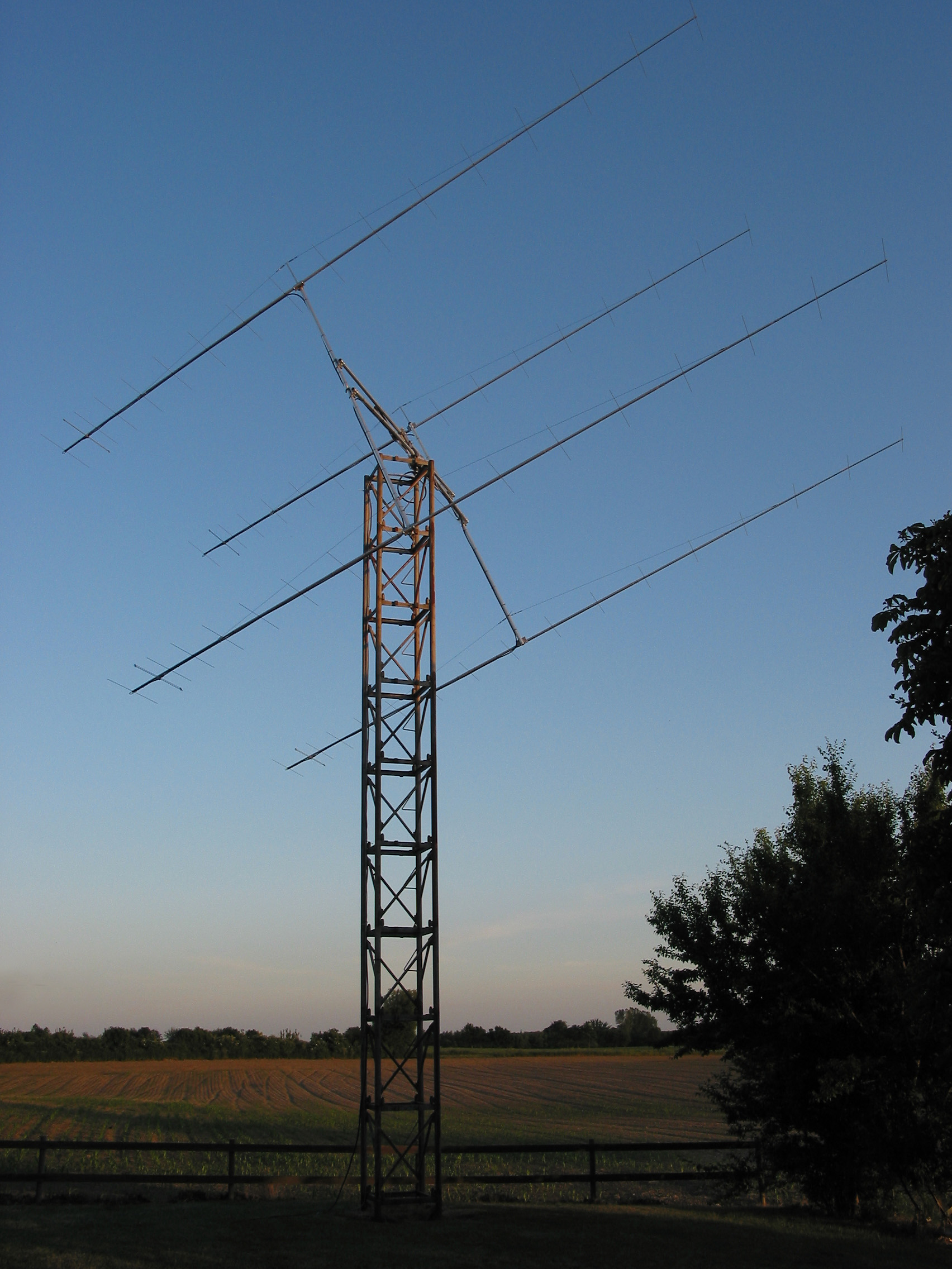
The common thread across repeater access, moonbounce (EME), meteor scatter, and general weak-signal HF/VHF work is that both endpoints are known and fixed (or, for EME, predictable via ephemeris) and the link budget is the whole game. A Yagi’s forward gain adds directly to that budget on both transmit and receive — 12–15 dB of gain over an omnidirectional reference is not a marginal improvement, it is very often the entire difference between decodable and not. EME is the limiting case: path loss to the moon and back is around 250+ dB at 144 MHz, so every stacked, long-boom Yagi in the array (the four 17-element Yagis in this volume’s lead photo are exactly this kind of structure) is there because gain-per-dollar-per-square-foot-of-tower-footprint is the only lever available once the moon is the reflector. Meteor-scatter work leans on the same arithmetic on a shorter timescale — the burn is short and weak, and every dB the antenna adds is a dB the decoder doesn’t have to find from noise. A directional antenna’s rear null matters here too, in a way an omnidirectional antenna cannot offer: rejecting 20+ dB of signal from behind materially improves the receive noise floor when the noise source (a repeater’s own transmitter feedback path, a nearby population center, a terrestrial interferer) sits opposite the wanted signal.
4.2.2 VHF/UHF contesting
Contest scoring rewards distance and multiplier count, and a rotatable Yagi is how a station works stations in every direction over a contest weekend without needing a separate antenna per bearing. The mechanism is the same link-budget argument as above, but the operational detail that matters for contesting specifically is speed of re-aim: a contest station is constantly swinging the beam to chase a new multiplier or a marginal path, so the rotator’s slew speed and repeatable accuracy (§4, §5) are as much a contest tool as the antenna’s gain figure. A 9-element 2 m Yagi against an omnidirectional vertical is worth on the order of 12 dB in a contest QSO — the difference between a station that’s workable and one that isn’t on a band where propagation is rarely generous.
4.2.3 Satellite work with crossed Yagis for circular polarization
Amateur satellites (and the ISS packet/APRS digipeater, and most LEO FM birds) use circularly polarized downlinks specifically because a satellite’s attitude relative to a ground station rotates continuously along its pass — a fixed linear polarization on the ground would fade in and out of null as the relative polarization angle sweeps through 90°. Two Yagis mounted at 90° to each other on the same boom, fed with a 90° phase difference between them, synthesize circular polarization from two linear elements: the mechanism is the same quadrature-feed principle used in any crossed-dipole or turnstile circularly-polarized antenna, just built from Yagi elements instead of simple dipoles to add gain on top of the polarization match. The gain matters because LEO satellite downlinks run milliwatts to a few watts from a battery-and-solar-powered platform hundreds of kilometers up — every dB of ground-station gain buys margin the satellite doesn’t have to spend on its own transmitter. This is squarely the companion Satellite Antennas & Rotators dive’s home turf for the antenna geometry (turnstile, eggbeater, and crossed-Yagi designs, and the az/el rotator hardware that tracks a pass) — see Vol 1 there for the full treatment; this volume’s job is only to place “crossed Yagi for circular polarization” correctly among the Yagi’s best-case uses.
4.2.4 Long-distance 2.4 / 5 GHz Wi-Fi links
A Yagi at 2.4 or 5 GHz is small enough (a few tens of centimeters of boom) to be a genuinely practical point-to-point solution, and the same link-budget arithmetic that makes it valuable for EME makes it valuable here: a 5+ km outdoor Wi-Fi bridge between two fixed, surveyed, line-of-sight points is squarely a Yagi-at-both-ends (or Yagi-to-panel, or Yagi-to-dish for the longer runs) problem, and it is routinely solved that way in wireless ISP and long-haul telemetry deployments. The Yagi’s directivity is a feature here in a second sense beyond gain: a narrow beam at both ends means neither radio illuminates its neighbors’ spectrum any more than necessary, which matters in the increasingly crowded unlicensed 2.4 GHz band. The same directional-antenna-at-distance logic extends to wireless security auditing platforms that pair a 2.4/5 GHz Yagi with a directional receiver to extend a site survey’s effective range well past line-of-sight — a use case documented in the RF tradecraft literature in the Hack Tools peer project, not repeated here.
4.2.5 Direction-finding
A Yagi’s sharp forward lobe and (especially) its deep rear null make it a workable direction-finding tool at VHF/UHF: sweep the beam and watch signal strength peak (or null) as the antenna crosses the bearing to the source. It is not the most precise DF tool available — a small loop’s null is sharper in relative terms, and dedicated Doppler DF systems beat a swept Yagi outright — but a hand-held or mast-mounted Yagi is cheap, requires no specialized DF hardware, and is routinely adequate for narrowing a bearing to a transmitter, a repeater interferer, or (in a public-safety or emergency context) a distress beacon.
4.2.6 Emergency and public-safety use
A directional 2 m or 70 cm Yagi pointed at a known regional repeater is a standard extension technique when a handheld’s rubber duck or a base station’s omnidirectional vertical isn’t closing a marginal link — a served-agency communications trailer, an EOC rooftop antenna, or a portable repeater-access setup at a disaster staging area gains the same 10+ dB the point-to-point case above describes, and in an emergency-communications context that 10 dB is very often the difference between “I can relay traffic” and “I can’t reach the repeater at all.” The tradeoff, worked through fully in §3, is that this only works cleanly when the repeater’s bearing is known and fixed; a Yagi is the wrong tool when the served agency’s location (and therefore the needed bearing) is itself mobile.
4.3 Worst-case use, equally seriously
The properties that make a Yagi win above are exactly the properties that make it the wrong antenna in a specific, predictable set of situations. Treating those situations with the same seriousness as the best cases is the only way to actually use this volume as a decision tool rather than a sales pitch.
4.3.1 Omnidirectional coverage
A Yagi’s entire value proposition is concentrating radiation into one direction; asking it to cover every direction defeats the design at the physics level, not just the practical level. Scanning, all-direction Wi-Fi coverage, or any application where the signal source’s bearing is genuinely unknown or constantly changing wants a discone (see the companion Discone & Wideband dive) or an omnidirectional vertical (see the companion Fixed Vertical Monopoles dive) instead. This is not a close call the way some of the tradeoffs below are — it is a category error to reach for a Yagi here at all.
4.3.2 HF on a residential lot — quantified
This is the tradeoff most likely to be underestimated by someone used to VHF/UHF Yagi dimensions. Vol 2’s boom-length-vs-gain table gives a 3-element Yagi a boom of roughly 0.4λ; at 20 m (14 MHz), 0.4λ is close to 24 feet (~7.3 m) of boom, and that is before adding the driven and reflector elements’ own length (each roughly 33 feet / 10 m tip-to-tip on 20 m) or the turning radius the whole rotating structure sweeps through — DX Engineering’s and Hy-Gain’s own HF Yagi spec sheets routinely list turning radii in the 14–20 foot range for exactly this reason. A structure that occupies a 40+ foot diameter circle when it rotates, mounted 30+ feet in the air on a tower rated to carry and turn it, is a project most residential lots — certainly anything on a suburban quarter-acre, and often anything inside a municipality with setback rules — simply cannot accommodate, quite apart from any HOA restriction. Lower in frequency, the problem stops being merely difficult and becomes close to a physical absurdity for an amateur station: a full-size 3-element Yagi on 80 m needs a boom on the order of 48 feet, and on 160 m close to 100 feet, with element tip-to-tip lengths in the 130–260 foot range per element — structures that exist at professional broadcast and military installations, essentially never at an amateur QTH. An amateur wanting directional gain on 80 or 160 m reaches for a phased vertical array, a receive-only directional antenna paired with an omnidirectional transmit vertical, or simply accepts an omnidirectional pattern; a low-band rotatable Yagi is not a realistic option, full stop.
4.3.3 Mobile operation
A Yagi bolted to a moving vehicle fails for a reason that has nothing to do with RF: a multi-foot boom with elements projecting a foot or more to each side is a road hazard and a low-bridge/garage hazard before it is anything else, and the vehicle’s own motion makes maintaining an aim on a fixed bearing meaningless in any case. Portable VHF Yagis exist (the Arrow 144-3, MFJ’s 6 m portable Yagi) but they are unambiguously set-up-and-operate antennas — deployed at a stop, aimed by hand, worked, and struck before the vehicle moves again — not something used while driving. The companion Portable & Mobile Monopoles dive’s whip and screwdriver-antenna family exists precisely because mobile operation wants an omnidirectional, low-profile antenna that survives being driven at speed; a Yagi is not competing for that job.
4.3.4 Indoor installation and near-field corruption
A Yagi’s published pattern is a free-space (or over-ideal-ground) prediction, and it holds only to the extent the near field around the antenna is actually clear. Mount a VHF/UHF Yagi inside a room and every wall stud, wire run, HVAC duct, and piece of furniture within roughly a wavelength becomes a parasitic re-radiator the NEC model never saw — the antenna’s own Vol 2-derived gain and F/B figures simply do not apply once the surrounding near field is that corrupted. The practical consequence documented across the amateur literature is 3–6 dB of forward gain lost to nearby reflectors even in comparatively benign cases (a Yagi mounted too close to a building’s own exterior wall), and indoor installation is a materially worse version of the same problem: metal ductwork, rebar in concrete floors, and the building’s own electrical wiring are far closer and far more numerous near-field disturbers than an exterior wall alone. An indoor VHF antenna wants a design that doesn’t depend on a clean near field to begin with — a roll-up J-pole or Slim Jim, or a simple dipole — not a Yagi whose entire value proposition is a pattern the room has already scrambled.
4.3.5 Multi-direction operation without a rotator
A fixed Yagi is a bet on one bearing (or a small handful, if you’re willing to physically re-orient it between contacts). That bet pays off cleanly for a station with one dominant use case — a repeater always in the same direction, a regular DX path — and pays off badly for a station that regularly wants to work multiple, materially different bearings. The rotator is not optional machinery bolted on for convenience in that second case; it is the component that makes “one Yagi, many directions” actually work, and its absence is a real argument for either accepting a fixed bearing or reaching for an omnidirectional antenna instead. §5 works through what a rotator actually needs to do the job.
4.3.6 SOTA / POTA — where deploy time matters more than gain
Summit and park activations run on a tight clock: the operator typically wants to work a modest pileup and pack out, not spend twenty minutes on antenna geometry. A packable VHF Yagi (the Arrow 144-3, at roughly a kilogram) is a legitimate SOTA/POTA antenna and does deliver real gain over a roll-up J-pole or a simple dipole — but assembling a multi-element boom-and-element structure, aiming it by hand or compass, and re-aiming it every time the wanted station moves is a five-plus-minute operation next to a roll-up dipole’s thirty seconds. For an activator whose real constraint is battery life, daylight, and the hike back down, that time cost is often the deciding factor, and the honest recommendation is: reach for the Yagi specifically when the goal is VHF DX or working a specific fixed repeater from the summit, and reach for something faster to deploy for a routine activation where any workable contact counts the same as a hard-won one.
4.4 The aiming discipline — beamwidth, error, and the case for a rotator
This is the volume’s spine, and it starts from a number Vol 2 already derived: HPBW falls from roughly 50° at five elements to 35° at nine, 22° at fifteen, and 12° at twenty-eight. Those numbers are frequently quoted and rarely worked through to their operational consequence, which is that a higher-gain Yagi is also a less forgiving one, and the forgiveness a broader beamwidth buys is a real, quantifiable form of value that a raw gain figure does not capture.
4.4.1 Quantifying the cost of a pointing error
Antenna engineering has a standard, widely used approximation for how much gain a directional antenna loses when it is pointed off its design bearing by some angle θ, relative to its HPBW: the parabolic (Gaussian-beam) pointing-loss formula
L(dB) ≈ 12 × (θ / HPBW)²
This is the same formula satellite ground-station engineers use to budget dish mispointing loss, and it holds because a well-formed main lobe is very nearly parabolic (in dB) near boresight — by construction, the formula gives exactly 3 dB of loss at θ = HPBW/2, which is the definition of the half-power beamwidth. It stops being trustworthy once θ pushes past roughly the first null, because past that point the antenna isn’t attenuating along a smooth lobe anymore — it’s delivering whatever the real sidelobe or backlobe structure happens to provide at that bearing, typically 10–20 dB below the main-lobe peak for a well-designed Yagi (see Vol 2’s sidelobe table).
Working the formula through the same worked example the task brief poses — a 30° aiming error — against four Yagis from Vol 2’s HPBW table makes the point concrete:
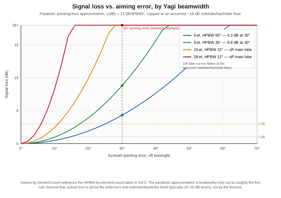
A 5-element Yagi (50° HPBW) pointed 30° off its intended bearing loses 4.3 dB — a real but survivable hit, well within what a strong signal or a modest power increase absorbs. A 9-element Yagi (35° HPBW) at the same 30° error loses 8.8 dB — getting serious, on the order of losing a full S-unit and then some. A 15-element Yagi (22° HPBW) at 30° off has been rotated essentially past its main lobe entirely — 30° is larger than the full beamwidth itself, so the antenna isn’t delivering a “somewhat attenuated” signal at that bearing, it’s delivering whatever the sidelobe structure happens to radiate there, plausibly 15–20 dB down from peak. A 28-element EME-class Yagi (12° HPBW) is in the same position at a far smaller error — a 30° miss is two and a half beamwidths off, deep into backlobe territory.
That progression is the entire case for taking rotator accuracy seriously in direct proportion to how many elements you bought. The formula also runs the other way, which is the more useful design question in practice: how much pointing accuracy does a given Yagi actually need to keep its aiming loss under, say, 1 dB? Solving 12 × (θ/HPBW)² = 1 gives θ ≈ 0.289 × HPBW. For a 5-element Yagi (50° HPBW) that’s about 14.4° of tolerable error — genuinely forgiving; a hand-aimed portable Yagi, or a cheap rotator with real backlash, comfortably clears that bar. For a 15-element Yagi (22° HPBW) the same 1 dB budget allows only about 6.4° — which is a real engineering requirement, not a rounding error, and pushes the aiming chain (rotator mechanical accuracy, controller readout resolution, and the operator’s own compass calibration against a known reference bearing) toward genuinely precision hardware. For a 28-element EME Yagi (12° HPBW) the 1 dB budget shrinks to about 3.5°, which is why EME and other serious weak-signal VHF/UHF operations specifically call out rotator systems with fine-resolution digital readout and calibration procedures (§5) rather than treating “point it roughly at the right compass heading” as adequate.
4.4.2 “More gain is not automatically better”
This is where the choosing question from §2–§3 and the aiming question fold back into each other. A rotator is not a binary yes/no proposition — every rotator has some real-world pointing accuracy, set by gear backlash, controller resolution, compass calibration drift, and (for a manually-read compass-and-protractor setup with no digital feedback at all) simple human error in reading a bearing off a map. If an operator’s actual achievable pointing accuracy is, generously, ±10°, then a 15-element Yagi (22° HPBW) is running a real risk of landing in the “past the main lobe” regime on any bearing that isn’t touched up carefully, while a 9-element Yagi (35° HPBW) at that same ±10° accuracy stays solidly on the shoulder of its main lobe with a modest, predictable loss. The blunt version of the conclusion: for an operator without a precision rotator and calibration discipline, a broader-beamwidth, lower-element-count Yagi very often delivers more usable signal, more of the time, across the range of bearings actually worked, than a narrower-beamwidth Yagi whose extra gain is only realized when the aim is spot-on. The extra gain a long-boom Yagi promises on a spec sheet is a peak figure; the antenna most operators actually experience is an average-over-actual-pointing-error figure, and those two numbers diverge fast as HPBW narrows. This is not an argument against long-boom Yagis — EME and serious contest stations correctly reach for every dB of peak gain they can get, because they also invest in the rotator and calibration discipline that keeps the beam close enough to boresight to realize it. It is an argument against buying beamwidth you can’t aim.
4.5 Rotator selection — wind load and turning moment, not gain
The instinct many operators bring to rotator shopping is to size the rotator to the antenna’s gain figure — a bigger, higher-gain Yagi must need a bigger rotator. That instinct is wrong on the mechanism. A rotator’s job is to overcome wind force acting through a lever arm; it has no way to sense or care about gain. The two quantities that actually determine rotator sizing are the antenna’s wind load (its effective frontal area presented to the wind, published by every serious manufacturer as a sq. ft. figure at a stated survival wind speed) and the turning moment that wind load develops at the mast, which depends on where that area sits relative to the mast — a long boom puts area far from the pivot point, which is exactly what a lever arm does to torque.
4.5.1 The mechanism: why boom length compounds the problem
Wind force on a flat or cylindrical structure scales with its frontal area and the wind’s dynamic pressure — this is standard fluid-dynamics territory, and it’s why every rotator and antenna manufacturer publishes wind load as an area figure rather than a raw force, letting the buyer match a rotator’s rated capacity (sq. ft. at a stated survival speed) directly against an antenna’s published wind load. But the rotator’s gear train doesn’t feel force — it feels torque, force multiplied by the distance from the pivot to where that force acts. A boom-mounted Yagi’s wind-load area is distributed along the boom, so a longer boom doesn’t just add more area (which the wind-load figure already captures); it also increases the average distance from the mast to that area, multiplying the torque demand beyond what the wind-load number alone suggests. Two Yagis with similar published wind-load figures can therefore impose meaningfully different actual torque on a rotator if one has that area concentrated near the mast and the other has it spread out along a long boom.
Four real, vendor-published Yagis make the point concretely:
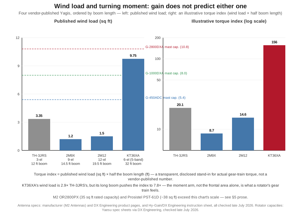
The M2 2M9X (9-element, 14.5 ft boom, 14.1 dBi) carries a published wind load of just 1.2 sq ft and sells for $403.99 as of late July 2026 (per M2’s own site, m2inc.com). Step up to the M2 2M12 (12-element, 19.5 ft boom, 14.9 dBi, $578.99 per DX Engineering) and wind load rises modestly to 1.5 sq ft — VHF elements are thin enough that even a longer boom stays a light wind-load package. The Hy-Gain TH-3JRS (a 3-element 10/15/20 m HF tribander, 12 ft boom) is a useful counter-example to a too-clean “boom length alone decides it” story: despite the shortest boom of the four, its thicker HF-gauge aluminum elements give it a published wind load of 3.35 sq ft, nearly 3× the much-longer-boomed 2M12 — a reminder that element mass and diameter matter independently of boom length, and that comparing wind load across frequency bands (thin VHF tubing vs. thick HF tubing) isn’t apples-to-apples. Where boom length dominates cleanly is the M2 KT36XA (a 6-element, 5-band HF Yagi in the classic KT34XA lineage, 32 ft boom): its published wind load of 9.75 sq ft is 2.9× the TH-3JRS’s, but because that area is spread across nearly three times the boom length, the illustrative torque index in the figure — wind load times half the boom length, a transparent proxy for the actual moment arm, not a vendor torque number — runs 7.8× higher than the TH-3JRS’s. That’s the mechanism worth internalizing: a long-boom, high-gain Yagi can impose far more actual turning demand on a rotator than a short-boom antenna of broadly similar gain, even when their published wind-load figures look comparable. (Both the KT36XA and the TH-3JRS showed “Not Available” for direct order at DX Engineering when checked in late July 2026, though their spec sheets remain published; treat their current buyability, not their published mechanical specs, as the item to re-check.)
4.5.2 Rotator families and honest capacity framing
Sizing a rotator correctly means matching its published wind-load and torque capacity against the antenna’s published wind load and against a realistic assessment of your local design wind speed — a coastal or Great Plains installation wants headroom a sheltered suburban lot may not need. The following families, checked live against vendor and manufacturer pages in late July 2026, span the amateur range from a single small VHF Yagi to an EME-class HF array:
Light duty — Yaesu G-450ADC. $429.99 at DX Engineering; rated wind load 10.8 sq ft mounted inside a tower, 5.4 sq ft mast-mounted (Yaesu’s own copy rounds this to “about 10 sq ft” tower-mounted — the same spec, quoted less precisely); 516 in-lb of turning torque. This is the right-sized rotator for the 2M9X-class antenna above, or any single small VHF/UHF Yagi — well matched, not over-built.
Medium duty — Yaesu G-1000DXA. $799.99 at DX Engineering; 23.7 sq ft tower-mounted / 8 sq ft mast-mounted wind load rating, 955 in-lb turning torque. This is the tier that starts to comfortably cover a 2M12-class long-boom VHF Yagi or a light HF tribander.
Heavy duty — Yaesu G-2800DXA. $1,769.99 at DX Engineering; 32.3 sq ft tower-mounted wind load, 10.8 sq ft mast-mounted, 2,170 in-lb turning torque, 661 lb maximum vertical mast load. This tier is sized for a genuine multi-element HF tribander or a stacked VHF EME pair.
Industrial / EME-class — M2 OR2800PX, Prosistel PST-61D, Alfa Spid RAK. The M2 OR2800PX is rated for up to 35 sq ft of wind load with 3,200 in-lb turning torque and 17,000 in-lb braking torque, but was listed “Not Available” for standard order at DX Engineering (custom-order only) when checked in late July 2026 — treat its price as unconfirmed rather than absent. The Prosistel PST-61D carries a wind-load rating around 38 sq ft (3.9 m²) with ~5,000 in-lb (564 N·m, per Prosistel’s own spec sheet) of braking torque, priced around €818 through a European retailer (GB Antennes) as of this check — a genuinely different market than the US-centric pricing above, and unconfirmed as a US landed price. The Alfa Spid RAK, a rotator in the same general capacity class as a Hy-Gain Tailtwister or a Yaesu G-2800, develops 1,400–3,240 lb-in of torque depending on drive voltage (12–18 VDC) and is commonly sold in the US bundled with a Green Heron controller rather than as a standalone unit at a fixed US list price — around €749 through a European retailer, again unconfirmed as a direct US price. This tier is what a KT36XA-class long-boom HF Yagi, or a stacked EME array like this volume’s lead photo, actually needs — and it is priced and sourced accordingly.
A honest flag on the historically dominant amateur brand. Hy-Gain’s Ham-IV and Tailtwister rotators were, for decades, the default recommendation at this capacity tier. MFJ Enterprises, which had owned the Hy-Gain (and Cushcraft) brands, ceased on-site manufacturing at its Starkville, Mississippi facility in May 2024; ITU Corporation announced its acquisition of the Cushcraft and Hy-Gain brands from MFJ in April 2026. Current production status, lead times, and pricing for Hy-Gain-branded rotators are genuinely in flux as of this writing — treat any specific Ham-IV or Tailtwister price you find quoted elsewhere as unconfirmed until checked against whatever ITU Corp’s current distribution looks like at the time you’re buying, not against this volume’s date.
Controller precision, separately from motor capacity. The rotator motor and gearbox determine torque and wind-load capacity; the controller determines how precisely you can read and repeat a heading, which is the other half of the §4 aiming-accuracy requirement. The Green Heron RT-21 ($649.00 direct from the manufacturer, greenheronengineering.com, checked late July 2026) is a universal digital controller, sold in model variants matched to Yaesu, Hy-Gain/CDE, M2, and Alfa Spid rotators, with a display resolution down to a tenth of a degree. That resolution is a readout and repeatability figure, not a claim that the mechanical system points to a tenth of a degree — real-world accuracy still depends on the rotator’s own backlash and a correct compass calibration against a known reference bearing — but pairing a fine-resolution controller with a mechanically stiff rotator is exactly how a 15- or 28-element Yagi’s §4 accuracy requirement (6.4° and 3.5° respectively, for a 1 dB aiming-loss budget) gets met in practice, rather than eyeballed.
The decision this section reduces to: look up the antenna’s published wind-load figure, apply the boom-length-as-lever-arm caution above if the boom is unusually long for its wind-load class, add margin for your actual local wind exposure, and buy the rotator (and, if aiming accuracy matters for the Yagi you chose, the controller) sized to that number — never to the antenna’s gain figure. Vol 5 carries the full ranked commercial-buy survey across rotators, masts, and coax; this section’s job was only the sizing logic.
4.6 Power handling — where it actually lives
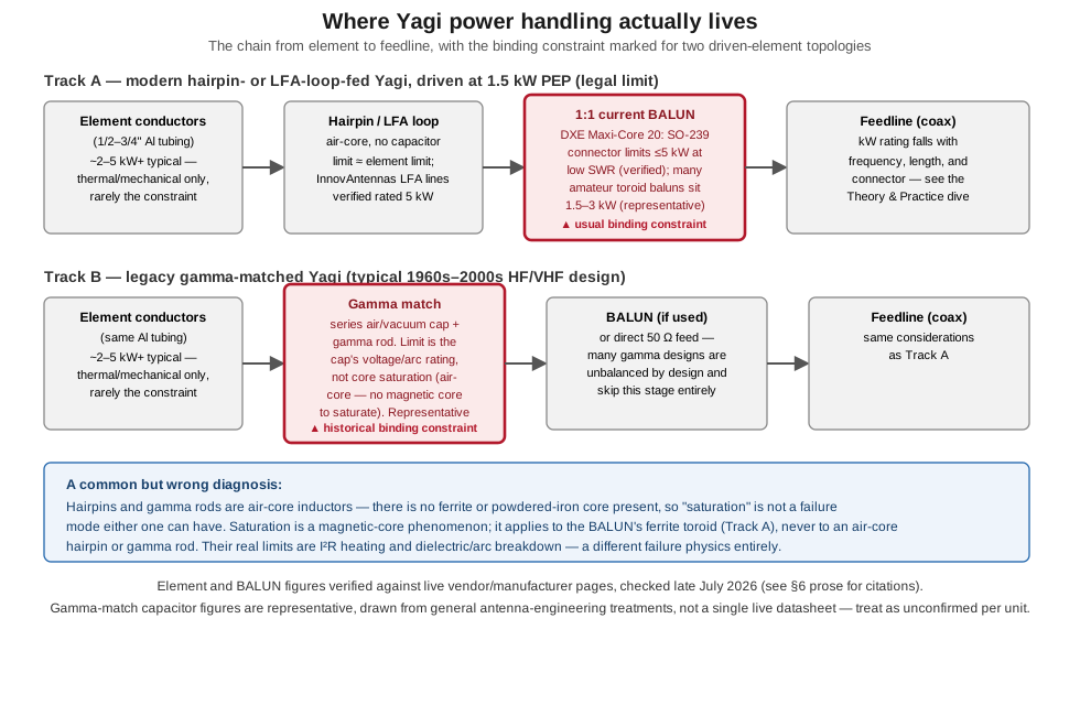
Ask a newcomer where a Yagi’s power limit lives and the answer is almost always “the elements” — thick aluminum tubing feels like it should be the constraint. It essentially never is. Power handling in a real Yagi lives, in order of how often each stage actually turns out to be the binding constraint at legal-limit amateur power, in the matching network, the balun, and the feedline — with the elements themselves comfortably ahead of all three.
4.6.1 Element conductors
A Yagi’s elements are solid or tubular aluminum, sized mechanically for wind and gravity load as much as for RF — and at any power an amateur station can legally run, the elements’ own thermal and mechanical limits (multi-kilowatt territory for typical 1/2″–3/4″ tubing) sit far above anything downstream in the chain. This stage is included in the diagram mainly to rule it out: it is very rarely where a real installation’s power ceiling actually sits.
4.6.2 The matching network — where the real divergence is
This is where the two design philosophies in the diagram split hard. A hairpin match or an LFA loop driven element is, electrically, still just a conductor — a U-shaped stub of wire or tubing, or a folded loop, with no capacitor, no adjustable component, and no separate voltage-stressed part in the signal path. Its power handling is essentially the conductor’s own limit, which is why InnovAntennas’ LFA product lines are verified (via DX Engineering, wimo, and InnovAntennas’ own shop pages, all checked late July 2026) as rated for 5 kW across multiple bands — a figure that reflects “the loop is just more conductor,” not a component working near a stress limit.
A gamma match is a genuinely different animal: a series capacitor (historically an air-variable trimmed to value and then often replaced with a fixed cap, occasionally a vacuum unit on high-power designs) plus a parallel-mounted rod tapped onto the driven element, together forming an L-network that transforms the driven element’s low resistance up toward 50 Ω while canceling the reactance the offset tap introduces. The capacitor sees a real voltage swing across it in normal operation — general antenna-engineering treatments of the gamma match describe swings on the order of 200–400 V at moderate power levels, with the actual figure depending on the specific match geometry and drive power — and it is that capacitor’s own voltage and current rating, not anything about the elements, that historically set the gamma-matched Yagi’s power ceiling. This is a representative, not vendor-verified, figure — no live datasheet for a generic “gamma match capacitor” exists to check, because the component is typically homebrewed or bundled into a specific manufacturer’s specific antenna rather than sold as a standalone rated part; treat any specific power figure for a gamma-matched Yagi as needing verification against that particular manufacturer’s own spec sheet, not this volume’s generalization.
A physics correction worth making explicitly, because the wrong version of this claim is easy to reach for: neither a hairpin nor a gamma rod has a magnetic core. They are air-core structures — bent wire or tubing, nothing else — and “saturation” is specifically a magnetic-core phenomenon: a ferrite or powdered-iron core’s permeability collapses once the material’s domains are fully aligned, and that collapse is what “core saturation” refers to everywhere the term is used correctly (transformers, chokes, ferrite-loaded baluns). An air-core inductor has no such mechanism available to it, because there’s no magnetic material present to saturate — full stop. What actually limits a hairpin or gamma rod at high power is I²R heating (ordinary resistive loss in the conductor) and, for the gamma match specifically, dielectric or arc breakdown across the capacitor, which is a voltage-stress failure mode, not a magnetic one. The distinction matters because reaching for “it saturated” as a diagnosis on an air-core Yagi component sends a troubleshooting effort in the wrong direction entirely — there is no core to inspect, and the real culprits (a loose or corroded hairpin connection heating under RF current, or a gamma capacitor arcing under SWR-driven voltage stress) are found by checking for heat and arcing, not permeability.
4.6.3 The balun — usually the actual binding constraint at legal limit
For a modern hairpin- or LFA-fed Yagi driven at legal-limit power (1.5 kW PEP), the 1:1 current balun at the feedpoint is, in practice, the stage most likely to be the tightest constraint in the whole chain. DX Engineering’s own Maxi-Core 20 series datasheet (checked late July 2026) states plainly that the assembly’s SO-239 connector “limits power handling to 5 kW or less at low SWR” — a genuinely high verified ceiling, and comfortably above the legal limit — but that figure describes DX Engineering’s specific high-end current-balun design at low SWR; many simpler amateur toroid-wound baluns on the market are rated in the 1.5–3 kW range (a representative figure drawn from the general product category, not a single verified datasheet, since “amateur balun” spans a wide range of designs and ferrite-mix choices). The practical takeaway: a well-specified, verified-5-kW balun genuinely is not the constraint at legal limit, but it’s the stage where a builder is most likely to have quietly under-specified a component relative to everything else in the chain, simply because the elements and the hairpin/LFA match are both so comfortably over-built by comparison. Check the specific balun’s own rating — don’t assume “it’s just a balun” means it automatically clears legal limit.
4.6.4 Feedline
Coax power handling falls with frequency and rises with conductor size and dielectric quality — RG-8X, LMR-400, and Heliax occupy successively higher power-handling and lower-loss tiers at any given frequency, and a long run at UHF is where the loss (not the raw power rating) usually becomes the operationally relevant number rather than any hard power ceiling. This is coax-selection territory the companion Theory & Practice dive’s transmission-line material owns in depth; the relevant point for this chain is only that feedline sits at the end of the chain, and a well-chosen line for the frequency and run length in question essentially never becomes the binding constraint before the balun does.
4.6.5 The M2 “7M9SSB” entry — a garbled record, corrected
This dive’s migrated seed material carried a commercial power-rating table with an entry for “M2 Antennas 7M9SSB, 9-element, 7 m band, $480, premium tier.” There is no amateur 7-meter band, anywhere — the nearest amateur allocations are 6 m (50–54 MHz in the US) and, in a handful of countries, a narrow 4 m allocation near 70 MHz; “7 m” corresponds to no ITU amateur allocation at all. Checking M2 Antennas’ own current catalogue (m2inc.com) and DX Engineering’s M2 listings, live in late July 2026, turns up no model called 7M9SSB and no 7-meter-band product of any kind. What does exist, and almost certainly what the garbled entry was trying to describe, is M2’s real historical 2 m 9-element Yagi line, the 2M9SSB / 2M9SSBFM — a genuine, well-regarded product that DX Engineering’s own current listings confirm has since been replaced by the 2M9X (which folds both the SSB/CW/digital and FM polarization configurations into a single dual-purpose antenna), currently $403.99 direct from M2 (checked late July 2026), 14.1 dBi gain on a 14.5 ft boom, rated for 1.5 kW. The most likely explanation is a simple transcription error — a “2” corrupted to a “7” somewhere upstream of this dive’s migrated source — compounded by a band designation and a price that don’t correspond to any real M2 product. Treat the original table’s entry as fully retracted; the real, current, verified figure for that product family is the 2M9X’s $403.99 and 1.5 kW rating above.
4.7 Where this volume hands off
This volume took Vol 2’s gain, pattern, and beamwidth numbers and asked what an operator actually does with them. The best- and worst-case sections (§2–§3) worked through why the Yagi’s directivity and gain win at point-to-point links, EME, contesting, satellite work, and long-distance microwave bridges — and why that same directivity is a liability for omnidirectional coverage, HF on an ordinary lot, mobile operation, indoor use, and any deploy-fast SOTA/POTA activation where aiming time is the scarce resource. The aiming discipline (§4) turned Vol 2’s HPBW table into an operational requirement: a 30° pointing error costs a 5-element Yagi 4.3 dB and a 15-element Yagi its entire main lobe, and the honest conclusion — that a broader-beamwidth Yagi often delivers more usable signal than a narrower one to an operator without precision aiming — is a genuine engineering tradeoff, not a hedge. Rotator selection (§5) is driven by wind load and turning moment, never by gain, and a long-boom high-gain Yagi can demand far more actual torque than its published wind-load figure alone suggests, because boom length is a lever arm. Power handling (§6) lives in the matching network, the balun, and the feedline, in that rough order of how often each is the actual constraint at legal limit — not in the elements, and a hairpin or gamma rod’s real limit is resistive heating and (for the gamma capacitor specifically) dielectric/arc breakdown, never magnetic-core saturation, because neither component has a core to saturate.
Vol 5 closes out this dive with the hands-on side: the step-by-step DIY build for a 5-element 2 m Yagi, the ranked commercial-buy survey across every price tier this volume deliberately left alone, and the companion gear — masts, coax, and thrust bearings — that every rotator-mounted Yagi in this volume depends on.
4.8 Resources
- ARRL Antenna Book (25th+ ed.), the Yagi and rotator-selection chapters — the canonical amateur treatment of wind load, turning radius, and mechanical sizing this volume’s §5 builds on.
- DX Engineering product and instruction-sheet pages (Yaesu, M2 Antennas, Hy-Gain rotators and Yagis; DX Engineering Maxi-Core baluns) — the live vendor source for every rotator and antenna spec figure checked in this volume, late July 2026.
- M2 Antennas (m2inc.com) — manufacturer’s own current catalogue, checked to confirm the 2M9X’s specs and price and the absence of any “7M9SSB” or 7-meter-band product (§6.4).
- InnovAntennas (innovantennas.com) and wimo.com — LFA Yagi power-rating confirmation (5 kW, multiple models).
- Green Heron Engineering (greenheronengineering.com) — RT-21 controller specifications and direct price.
- GB Antennes and RF Hamstore — European retailer listings used for Prosistel PST-61D and Alfa Spid RAK specifications and indicative (non-US) pricing.
- ARRL news coverage of the MFJ Enterprises manufacturing shutdown (2024) and the ITU Corporation acquisition of the Cushcraft and Hy-Gain brands (April 2026) — the basis for this volume’s caution on current Hy-Gain rotator availability and pricing.
- The satellite antenna geometry and az/el rotator hardware referenced in §2 belong to the companion Satellite Antennas & Rotators dive; the omnidirectional alternatives referenced in §3 belong to the companion Discone & Wideband and Fixed Vertical Monopoles dives.
Comments (0)