Discone & Wideband Antennas · Volume 5
Build, Measure and Buy
A build sheet in which four parameters of six are confirmed, a verification procedure that measures the one property a cone is good at keeping, a pattern check that cannot work because the antenna is a body of revolution, and a market in which every checkable price was low in the same direction
5.1 About this volume
Four volumes of theory arrive here. Vol 1 found the cone angle stated at twice its value and separated the two bandwidths. Vol 2 found a feed-gap rule out by a factor of thirty and derived a spoke count with no frequency in it. Vol 3 found the elevation pattern printed upside down. Vol 4 found a biconical at twice its stated size and a sleeve section whose three products include none that can be shown to be a sleeve. This volume builds something, tests it, and buys something.
After all that, the most useful thing to say about the build is that most of it is right.
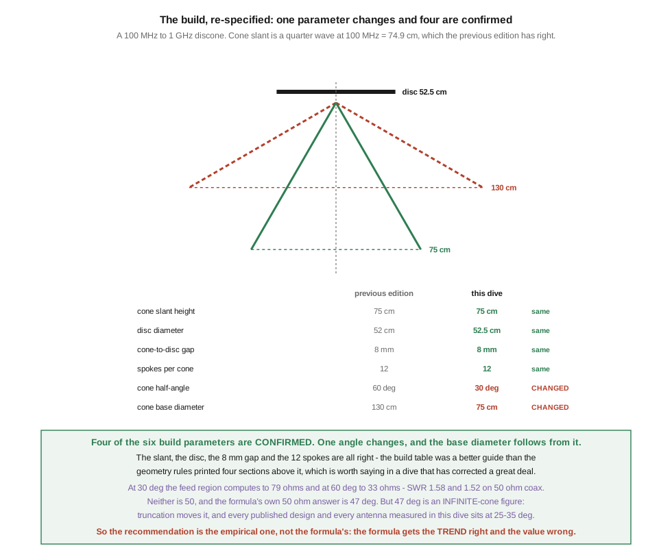
Four of the six build parameters are confirmed. §2 checks them: the cone slant, the disc diameter, the 8 mm gap and the twelve spokes all survive. One angle changes, and the cone’s base diameter follows from it. ⭐ That matters to record, because a dive which has corrected this much accumulates a momentum toward finding more, and over-correction is a named failure mode in this program. The build table was a better guide than the geometry rules printed four sections above it.
The verification procedure is a real test of the wrong property. §5 takes it apart. It is an SWR sweep, it will pass, and it confirms the impedance behaviour — which is the property a cone is good at keeping and the one this dive never doubted. It says nothing about where the energy goes, which is what actually degrades. And its one pattern check instructs the builder to rotate the antenna, which cannot work on a body of revolution.
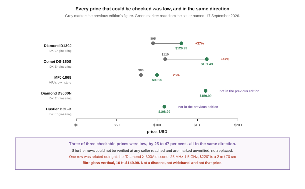
And the market’s prices were wrong in one direction. §6 gives what could be read from sellers on 17 September 2026. Of three prices checkable against the previous edition’s, three were low, by 25 to 47 per cent. Eight further rows could not be verified anywhere and are marked unverified rather than replaced. One row is refuted outright.
5.2 The build, re-specified
The target is the previous edition’s: a 100 MHz – 1 GHz discone from sheet aluminium and welding rod.
The cone’s slant height is a quarter wave at the lowest design frequency. At 100 MHz that is 74.9 cm, and the chapter’s 75 cm is right. Everything else follows from it and from the cone’s half-angle.
Table 1 — 2. The build, re-specified
| parameter | previous edition | this dive | |
|---|---|---|---|
| cone slant height | 75 cm | 74.9 cm | ✅ same |
| disc diameter | 52 cm | 52.5 cm | ✅ same |
| cone-to-disc gap | 8 mm | 8 mm | ✅ same |
| spokes per cone | 12 | 12 | ✅ same |
| cone half-angle | 60° | 30° | 🔴 changed |
| cone base diameter | 130 cm | 74.9 cm | 🔴 changed |
The two changes are the same change. Vol 1 §5 established that the chapter’s own construction text specifies a 30° splay from vertical while its table computes from 60°, and that the splay from vertical is the half-angle. Taking the 30° the text describes, base = 2 × slant × sin 30° = slant, so the cone’s base diameter equals its slant height — a pleasing coincidence at this one angle, and 74.9 cm rather than 130 cm.
Everything else is confirmed:
- The disc at 52.5 cm is
0.7 × slant, which Vol 2 §3 verified against the published rule. The chapter’s 52 cm is the same number rounded. - The 8 mm gap is the figure Vol 2 §4 vindicated against the chapter’s own geometry rule, which would have demanded 225–375 mm. The build table had it right and the rule had it wrong.
- Twelve spokes satisfies Vol 2 §5’s λ/10 criterion with margin — twelve gives 0.0654 λ of spacing in the active region against the 0.0982 λ that eight gives, and the criterion is met from eight spokes up, at every frequency.
5.2.1 The angle, and why this dive does not recommend the formula’s answer
There is a tension here that deserves stating rather than hiding, because it is the most interesting thing in the build.
Vol 1’s formula, Z₀ = 60 ln(cot(θ/2)), puts 50 Ω at 47°. The 30° specified above computes to 79 Ω, an SWR of 1.58:1 on 50 Ω coax. The chapter’s 60° computes to 33 Ω, an SWR of 1.52:1. On the formula’s own evidence, neither is as good as 47° would be.
⚠ This dive nevertheless specifies 30°, and the reason is that the formula does not fully apply. 60 ln(cot(θ/2)) is the characteristic impedance of the infinite conical line — the feed region — and a real discone is truncated, loaded by its radiation, and carries a finite disc rather than an infinite plane. Truncation moves the terminal impedance away from Z₀, and it moves it downward. The evidence that it does is direct and plentiful: every published design sits between 25° and 40°, the antenna measured from a photograph in Vol 1 §4 sits at 26.6°, and the commercial discones in §6 are all sold as 50 Ω antennas with a published SWR under 2:1. A 79 Ω antenna would not be.
⭐ So the formula gets the trend right and the absolute value wrong, and saying so is more useful than a confident 47°. It is exactly right that widening the cone lowers the impedance, which is what convicts the chapter’s 60°; it is not accurate enough to set the design point, which is empirical. Building at 47° on the strength of an infinite-cone formula would be this dive committing the chapter’s own error in the opposite direction.
Build it at 30°. It is what the chapter’s own construction text says, what the published range centres on, and what every antenna anyone has measured looks like.
5.3 The bill of materials
⚠ Prices below are estimates, not quotations, and are marked as such. The chapter’s BOM lists nine items summing to about $55 under a heading that says ”~$45”, which is the kind of internal disagreement that suggests neither figure was added up.
Table 2 — 3. The bill of materials
| part | specification | note |
|---|---|---|
| Aluminium sheet | 0.040″ 6061, ~30 × 30 cm, for the disc hub and apex block | |
| Welding rod, disc | 3/16″ × 26 cm, 12 off | the disc’s radius is 26.2 cm |
| Welding rod, cone | 3/16″ × 75 cm, 12 off | the slant height |
| Perimeter ring, disc | 12-gauge bare copper, ~1.65 m | π × 52.5 cm |
| Insulating spacer | PTFE or nylon, 8 mm thick | sets the gap — the one critical dimension |
| Apex hub | aluminium block, ~3 cm cube | and the reference for the gap rule |
| SO-239 chassis connector | or N, if the build is to be used above 500 MHz | |
| Hardware | stainless throughout | |
| Mast adapter | 1.5″ PVC stub, UV-stabilised | |
| Weatherproofing | self-amalgamating tape and a sealant over it |
Three notes on parts, two of which correct the chapter.
⚠ The connector choice is not free above 500 MHz. The chapter specifies an SO-239 and a PL-259 pigtail throughout, for an antenna it designs to 1 GHz. The UHF series is not a constant-impedance connector and is not specified for that range; every commercial discone in §6 that reaches 3 GHz uses N, and Diamond sells the same antenna in both SO-239 and N versions for exactly this reason. Use N if the build is meant seriously above about 500 MHz.
⚠ The cone needs no perimeter ring and the disc does. The chapter specifies it this way and Vol 2 §6 found the asymmetry defensible on an argument the chapter does not make: the cone’s rim is outside the active region at every frequency above the very bottom of the band, while the disc’s rim is always at its working radius.
✅ The 3/16″ rod is not specified by any source this dive found, and is carried forward as the chapter’s reasonable choice rather than as a verified figure. Vol 2 §6 lists spoke diameter among the dimensions nobody specifies.
5.4 Construction
Cut and drill the disc hub and the apex block first, because the 8 mm spacer between them is the one dimension the antenna is sensitive to and everything else hangs off the assembly.
Bend a 90° tab on one end of each of the 24 rods. The twelve disc rods attach to the disc hub and run horizontally to the perimeter ring. The twelve cone rods attach to the apex block and splay 30° from vertical — which, since the base diameter equals the slant height at this angle, means the rim of the finished cone is a circle of 74.9 cm diameter, 64.9 cm below the apex. Check the splay with a protractor against the mast, not by eye: Vol 1 is a volume about what happens when this angle is got wrong.
Assemble the feed last. The SO-239’s centre conductor goes to the disc hub and its shell to the cone apex block, through the PTFE spacer. The chapter’s §2.4 states this orientation correctly and warns that reversing it degrades performance — ⚠ the stated penalty of “1–3 dB” is unsourced and is not reproduced here, but the orientation itself is standard and is carried forward.
Fit a common-mode choke at the feedpoint. Vol 4 §4 gave the mechanism: the disc is a ground plane at 35 % of the diameter, and a small plane does not screen the feedline from the radiating structure the way a full one does. A string of mix-31 or mix-43 beads over the coax immediately below the connector is the usual answer; the BALUNs and UNUNs dive covers the winding in detail.
Check DC continuity across the connector before connecting anything. Vol 2 §7 could not establish whether commercial discones present a DC short, and a home-built one presents whatever its builder gave it. This is ten seconds with a multimeter and it matters to any bias-tee or DC-coupled front end downstream.
5.5 Testing it, and the property the sweep cannot see
The chapter’s verification is:
Test with the NanoVNA. Connect the NanoVNA to the coax. Sweep 80–1000 MHz. SWR should be < 2:1 across 100 MHz – 800 MHz; slightly higher at 800 MHz – 1 GHz; degraded beyond 1 GHz (the design limit).
⚠ This is a real test and it is worth doing. That needs saying plainly, because a previous dive in this program found a bench test that could not fail, and the temptation to find the same shape again is a failure mode. This one genuinely exercises the antenna: a mis-set cone angle, a wrong gap, a shorted feed or a bad connector will all show up in it. Do it.
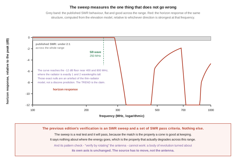
🔴 What is wrong is that it is the only test, and it measures the property that does not fail. This dive’s whole spine is that a discone’s impedance bandwidth and its pattern bandwidth are different intervals with different limits. The match is what a conical geometry is good at keeping — Wikipedia’s published account is “SWR is typically 1.5:1 or less over several octaves” — and the sweep confirms it. Meanwhile, from Vol 3’s model, the horizon response of this same structure across this same range:
Table 3 — 🔴 What is wrong is that it is the only test, and it measures the property that does not fail. This dive's whole spine is that a discone's impedance bandwidth and its pattern bandwidth are different intervals with different limits. The match is what a conical geometry is good at keeping — Wikipedia's published account is "SWR is typically 1.5:1 or less over several octaves" — and the sweep confirms it. Meanwhile, from [Vol 3](/discone-wideband/vol-3/)'s model, the horizon response of this same structure across this same range
| frequency | cone height | horizon response, relative to the peak |
|---|---|---|
| 100 MHz | 0.25 λ | 0.00 dB |
| 200 MHz | 0.50 λ | 0.00 dB |
| 250 MHz | 0.625 λ | 0.00 dB |
| 300 MHz | 0.75 λ | −2.92 dB |
| 500 MHz | 1.25 λ | −4.88 dB |
| 1000 MHz | 2.50 λ | −4.63 dB |
⚠ Those sampled frequencies sit between the model’s nulls, and the figure shows what lies between them. Where the radiator is exactly one or two wavelengths tall — about 400 MHz and 800 MHz on this build — the thin-radiator expression puts a perfect null on the horizon, and the plotted curve accordingly plunges to the floor of the chart. A fat, self-truncating cone will not do that. Those plunges are an artefact of the idealisation and are marked as such on the figure; what survives the caveat is the trend, which is that above 250 MHz the horizon stops being the strongest direction and does not become so again.
The sweep runs flat and passing across a range over which the antenna gives up several decibels in the direction the listener cares about. A builder who runs the chapter’s test and sees a clean sweep has confirmed the half of the antenna’s behaviour that was never in question.
🔴 And the one pattern check offered cannot work. The chapter says:
Pattern omnidirectional in azimuth (verify by rotating and observing constant signal level on a distant fixed source)
A discone is a body of revolution. Rotating it about its own axis changes nothing — not its geometry, not its pattern, not the received level. The instrument will read constant whatever the antenna’s azimuth pattern is, including if it has the deep disc-induced nulls Vol 3 §6 computed for the top of the band. To measure an azimuth pattern the source has to move relative to the antenna, or the antenna has to be carried around the source. Spinning it on its mast is a null operation.
5.5.1 What to test instead
Keep the SWR sweep, with the pass criteria stated as what they are — a check on construction, not a performance measure. ⚠ The chapter’s specific thresholds (“SWR < 1.5:1 across 100–500 MHz” and so on) have no source and are not reproduced; use them as a shape to compare against rather than as a specification.
Add a horizon-response comparison, which is the measurement this dive actually wants. Put a signal source at the horizon at a fixed distance — a low-power beacon, a handheld on a known frequency, or an off-air transmitter of known location — and compare the discone’s received level against a simple quarter-wave vertical for that band, swapping between the two. Repeat on as many widely separated frequencies as the source allows. The prediction this dive makes is that the discone matches the vertical near the bottom of its range and falls progressively behind it higher up, and that is a falsifiable statement a builder can test in an afternoon with an SDR and a step attenuator.
Add the DC continuity check from §4.
And record the spoke splay angle you actually built, because it is the parameter this whole dive turns on and nobody measures it after assembly.
⏳ None of this has been done. No measurement anywhere in these five volumes is first-hand, and the horizon comparison above is written as the procedure that would close the largest gap in the dive.
5.6 The market, dated
Everything in this section was read on 17 September 2026 from the seller named. Where a figure could not be verified it is marked unverified rather than filled in.
5.6.1 The prices that could be checked
Table 4 — The prices that could be checked
| model | previously printed | 17 Sep 2026 | source | |
|---|---|---|---|---|
| Diamond D130J | $95 | $129.99 | DX Engineering | +37 % |
| Comet DS-150S | $110 | $161.49 | DX Engineering | +47 % |
| MFJ-1868 | $80 | $99.95 | MFJ’s own store | +25 % |
| Diamond D3000N | not listed | $159.99 | DX Engineering | — |
| Hustler DCL-B | not listed | $108.99 | DX Engineering | — |
⭐ Three of three checkable prices were low, all in the same direction, by 25 to 47 per cent. That consistency is itself informative: unlike the antenna-tuners dive, whose errors ran both ways and looked invented, these read like real prices from an earlier year that were never refreshed. The correction is to date them, not to distrust them.
Two current products are missing from the chapter entirely — the Diamond D3000N, which is the wideband flagship of the line it does list, and the Hustler DCL-B. Also absent are the Diamond D130NJ (the N-connector version of its own top recommendation, which §3 argues is the one to buy for serious use above 500 MHz) and two Moonraker models.
5.6.2 The power ratings, which are wrong in both directions
Table 5 — The power ratings, which are wrong in both directions
| model | chapter’s rating | published rating |
|---|---|---|
| MFJ-1868 | 100 W | 200 W |
| Comet DS-150S | 250 W | 100 W |
| Diamond D130J | 200 W | 200 W on 144–1300 MHz; 20 W FM / 50 W PEP on 6 m |
🔴 Two of the three are wrong, by a factor of two, in opposite directions — the MFJ understated and the Comet overstated. The Comet error is the dangerous one: a builder trusting 250 W into an antenna rated 100 W is running two and a half times its specification.
⭐ And the Diamond row is right but incomplete in a way that matters more than either error. Diamond’s own specification derates 6 m by a factor of ten for FM and four for SSB. The chapter’s flat “200 W” hides that entirely, and 6 m is exactly the band an amateur is most likely to transmit on with a scanner discone.
5.6.3 What could not be verified
⚠ Eight rows could not be verified at any seller reached, and are marked unverified rather than replaced: Tram 1410, Workman 102, Watson WD-130, Sirio SD-1300U, Yaesu YDS-101, “Eikos Discone-Pro”, “Bonito MegaDiscone”, and “A.H. Systems wideband discone”.
Two of those deserve a note:
⚠ Sirio publishes no scanner or discone family. Its own site organises its catalogue as HF, VHF, UHF, Cellular, WLAN and ADS-B, and the SD-1300U does not appear. The model may exist in a European distribution channel this dive did not reach. Not declared fictitious.
⚠ A.H. Systems’ own antenna categories do not include discones. Its catalogue lists antenna kits, biconical, bilogical, current probes, dipole, H-field rods, horn, log periodic, loop, monopole and preamplifiers. The chapter lists “A.H. Systems wideband discone, 30 MHz – 6 GHz, $700–1500” in its buys table and “A.H. Systems wideband discones, 500 W+” in its power table. ⚠ Absence from a navigation menu is not proof of absence from a catalogue, so this is recorded as could-not-be-found rather than refuted — but it is the row this dive would check first with a direct enquiry, and Vol 4 §7 has already shown the 500 W figure to be the wrong expectation for instrument-grade antennas, one of which carries a plate reading P < 20 W.
🔴 And one row is refuted outright. The chapter lists “Diamond X-300A | 25 MHz – 1.5 GHz | $220 | Diamond’s heavier-duty model” among its mid-tier discones. DX Engineering’s listing for the X300A reads “Antenna, Vertical, Dual-Band Base/Repeater, Fiberglass, 2m/70cm, 200W, UHF Female/SO-239, 10.0 ft Height” at $149.99. It is a two-band fibreglass collinear, not a discone; it covers two amateur bands, not 25 MHz to 1.5 GHz; and the price is 47 % above the one printed. Wrong in category, in coverage and in price.
⚠ MFJ ceased on-site manufacturing on 17 May 2024, so the MFJ-1868’s $99.95 is remaining stock rather than continuing production. The antenna is a reasonable budget choice while it lasts; it is not a product line with a future.
5.7 What to avoid, and the warning that rejects its own recommendation
The chapter closes with three warnings. They fare differently.
⚠ “Ultra-cheap 10 GHz discones on Amazon” — the general caution against mislabelled marketplace antennas is sound and unverifiable in the particular. Carried forward as advice rather than as a finding.
🔴 “‘5G discones’ — 5G operates at 5 GHz and 28 GHz.” The premise is wrong. 5G NR occupies low-band allocations around 600–900 MHz, mid-band around 2.5–3.7 GHz (the n77 and n78 bands run roughly 3.3–3.8 GHz), and millimetre-wave bands around 24–40 GHz. “5 GHz” is a conflation of 5G with 5 GHz Wi-Fi, which is a different thing entirely and one of the more common errors in consumer RF writing. The advice — that “5G” on an antenna listing is usually branding — survives; its stated reason does not.
🔴🔴 And the third warning rejects the chapter’s own top recommendation. It reads:
“Multi-band miracle discones” with implausibly low prices ($30 for 25 MHz – 6 GHz) — the cone size required for 25 MHz operation alone is ~2.5 m slant; physics doesn’t allow it to be cheap.
Vol 1 §6 demolished the premise. Every commercial discone in §6 advertises a 25 MHz receive floor with an antenna 1.70 m tall or less — the Diamond D130J the chapter recommends among them. A quarter wave at 25 MHz is 3.00 m; none of these antennas is even close, and they are not lying, because the receive floor is a statement about an external-noise-limited regime rather than about resonance. So a 25 MHz claim does not imply a 2.5 m slant, and by the warning’s own logic the D130J would be a “multi-band miracle” too.
⭐ The instinct is still right and deserves a correct mechanism. Be suspicious of a $30 antenna claiming 25 MHz – 6 GHz — not because 25 MHz needs 2.5 metres, but because the upper end is where the cost lives. Reaching 6 GHz with a usable pattern requires fabrication tolerances, a constant-impedance connector and a feed-gap geometry that a $30 stamping does not have, and because — Vol 3 — nobody selling such an antenna is making any claim about the pattern at all. The right scepticism is about the top of the range, and the chapter aims it at the bottom.
5.8 Where this dive ends
Five volumes, and the corrections turned out to be the product.
A cone is wideband because a conical transmission line has the same impedance at every radius — not because that impedance tapers, which is what the chapter says and which would destroy the property. The impedance is 60 ln(cot(θ/2)), or twice that without a plane, and is a function of one angle. That angle is stated throughout the chapter at twice its value, in a build sheet that also states it correctly, with the dimension tables computed from the wrong reading and the construction steps describing the right one.
A finite discone has three lengths — a cone slant, a disc diameter and a feed gap — and they are its band edges. The slant sets the bottom, which can be bounded from published dimensions alone; doing so finds that every scanner discone on the market carries two bottom frequencies, a transmit floor just above the bound and a receive floor a factor of two below it that describes a noise regime rather than an antenna. The gap eventually spoils the match at the top, later than the pattern fails. And the disc is a ground plane at 35 % of the diameter, which is the entire reason the discone exists and the one advantage the chapter never names.
The elevation pattern is printed upside down. The maximum sits on the horizon until the cone passes five eighths of a wavelength and then leaves; the chapter’s 25–35° is a band the maximum crosses rather than a place it rests; and the use-case advice drawn from the inversion is backwards at the design frequency, with the most common case of all — a distant mountaintop repeater, subtending about a degree — classified as high-angle. Azimuth ripple is identically zero from the cone at every frequency, because its active ring scales with wavelength, and appears from the disc, whose radius does not.
And the spoke count, which reads like the most frequency-dependent parameter on the antenna, contains no frequency at all.
5.8.1 What this dive owes
- 🔴 No measurement here is first-hand. Every figure is computed and two of them are explicitly models. §5’s horizon comparison is written as the procedure that would close the largest gap, and it needs nothing more than an SDR, a step attenuator and an afternoon.
- 🔴 No NEC model. Vol 3’s elevation and azimuth results are stand-ins for the mechanism, clearly labelled, and a proper model of a fat self-truncating cone over a finite disc would replace them with numbers this dive would be willing to assert. That is the single most valuable thing anyone could add.
- ⚠ No independent accuracy review. Author and checker have been the same throughout, which every previous dive in this program found to be the weakest link.
- ⚠ Three unresolved sources: the primary origin of the dimensional rules, traced no further than two secondary works; the Rumsey 1957 convention-record paper, cited here from the verified 1966 book instead; and a primary reference for the sleeve antenna’s definition, without which Vol 4 §6’s terminology point stands as a question.
- ⚠ Eight unverified product rows and three unpriced EMC instruments, listed as such in §6 and Vol 4 §7. None was replaced with a guess.
- ⏳ Photographs of a build. There is no build to photograph yet. The four photographs in this dive are other people’s antennas.
5.9 Resources
- DX Engineering — the Diamond D130J, D3000N, D130NJ, Comet DS-150S, Hustler DCL-B and Diamond X300A listings and prices, read 17 September 2026.
- MFJ Enterprises — the MFJ-1868 listing, 25–1300 MHz receive and 50–1300 MHz transmit at 200 W, $99.95, read 17 September 2026. Note that MFJ ceased manufacturing on 17 May 2024.
- Diamond Antenna published specifications — the D130J’s 2 dBi nominal gain and its 6 m power derating, which §6 found the chapter flattening away.
- Armig G. Kandoian, Broad band antenna, US Patent 2,368,663 — the primary source, read in full for Vol 2.
- Jerry Hall, ed., The ARRL Antenna Book, 16th ed., and Paul Lee, The Amateur Radio Vertical Antenna Handbook, 2nd ed. — the two secondary works carrying the published geometry rules and the horizon-sensitivity statement Vol 3 rests on.
- NanoVNA, Vol 4 — the sweep technique §5 keeps, and the two-port method the horizon comparison would use for its reference measurements.
- BALUNs and UNUNs, Vol 5 — the common-mode choke §4 fits at the feedpoint.
- Antenna modeling software, Vol 1 — the NEC workflow that would close this dive’s largest debt.
- Receive-only loops, Vol 1 — why the 25 MHz receive floor in §6 is an honest specification rather than a marketing one.
- Log-periodic and structured wideband antennas — the directional wideband family, and the companion to this dive.
Comments (0)