BALUNs & UNUNs · Volume 2
Topology — Guanella, Ruthroff, and the Transmission-Line Transformer
Two ways to enforce balance and why forcing currents beats forcing voltages; what makes a transmission-line transformer categorically different from a wound transformer; the characteristic-impedance condition Z₀ = √(Z_in·Z_out) and the quarter-wave dip you get for ignoring it; Guanella's series-parallel N² ladder; what actually sets the low-frequency and high-frequency ends of the passband; and where a plain autotransformer is the honest choice
2.1 About this volume
Vol 1 established what has to happen at a feedpoint: keep current off the outside of the coax shield, and — separately — transform the antenna’s impedance to 50 Ω. This volume is about how, and it turns out that the entire modern family descends from two papers fifteen years apart.
The first is Gustav Guanella’s, in the Brown Boveri Review of September 1944 — “Novel matching systems for high frequencies”, pp. 327–329 — which introduced the transmission-line transformer and showed that groups of 1:1 units could be combined to give any ratio of the form N². The second is C. L. Ruthroff’s “Some Broad-Band Transformers”, Proceedings of the IRE, August 1959, pp. 1337–1342 (manuscript received 5 February 1959, revised 1 April 1959), written at Bell Telephone Laboratories in Holmdel, New Jersey, which developed the 1:1 and 4:1 unbalanced-to-unbalanced forms and the hybrids, and — importantly for this dive — published measured data.
Ruthroff’s own summary of what these devices were capable of, in 1959, is worth reading before any modern claim about balun bandwidth:
“Several transmission line transformers are described which have bandwidth ratios as high as 20,000:1 in the frequency range of a few tens of kilocycles to over a thousand megacycles. Experimental data are presented on both transformers and hybrid circuits.”
He also notes, in a sentence that should temper any assumption that a good balun must be big: “These transformers can be made quite small. Excellent transformers have been made using ferrite toroids having an outside diameter of 0.080 inch.” Two millimetres. The FT240-size cores this dive spends most of its time on are sized for power, not for transformer action.
Both names have since become adjectives — “a Guanella 4:1”, “a Ruthroff 4:1” — and in amateur usage they have drifted into rough synonyms for “current balun” and “voltage balun”. That drift is mostly harmless but it hides the actual distinction, which is not about who invented what but about which quantity the device forces to be equal. That is where this volume starts.
2.2 Two ways to enforce balance — currents or voltages
A balanced feed means the two antenna terminals are driven symmetrically. There are two ways to arrange that, and they are not equivalent.
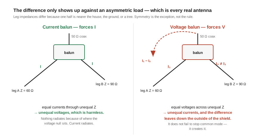
Force the currents. Build a device that guarantees the current leaving terminal A equals the current entering terminal B, whatever the load does. This is the current balun.
Force the voltages. Build a device that guarantees terminal A sits at +V/2 and terminal B at −V/2 with respect to the input’s ground reference. This is the voltage balun.
For a perfectly symmetric load the two give the same result, which is why the distinction went unremarked for years. The difference appears the moment the load is not symmetric — and no real antenna is. One leg is nearer the house than the other, or nearer a tree, or sloping differently, or the feedline is not perpendicular to the wire. Asymmetry is the normal condition.
Now the two behave differently in a way that matters:
- A current balun forces
I_A = −I_B. If the two halves of the antenna have unequal impedances, then equal currents through unequal impedances produce unequal voltages — the feedpoint voltage sits off-centre. That is harmless. Nothing about radiation cares where the voltage null is; what radiates is current. - A voltage balun forces
V_A = −V_B. Equal voltages across unequal impedances produce unequal currents. The difference between those two currents has to go somewhere, and the only path available is the outside of the coax shield. A voltage balun feeding an asymmetric load manufactures common-mode current.
This is the whole argument, and it is why the modern default is unambiguous. The voltage balun is not enforcing balance so much as asserting it — imposing a symmetry the antenna does not have, and letting the discrepancy escape down the feedline. The current balun enforces the quantity that actually matters and lets the voltage fall where the antenna wants it.
Put in the language of Vol 1: a current balun is a device whose common-mode impedance is high. A voltage balun’s common-mode impedance can be low, because the current-splitting path through its windings is part of how it works.
2.3 The current balun (Guanella)
Guanella’s insight was to stop thinking of the device as a transformer at all and think of it as a transmission line wound on a core.
Take a two-wire transmission line — a bifilar pair, a twisted pair, or a length of coax — and wind several turns of it through a ferrite toroid. Feed one end, load the other. Two things are simultaneously true:
- To the differential (transmission-line) mode, this is just a short length of transmission line. Its two conductors carry equal and opposite currents, their flux cancels in the core (Vol 1 §5), and the mode passes through as if the core were not there.
- To the common mode, the wound assembly is a cored inductor with a large series impedance.
So the device transmits the wanted signal along a transmission line while presenting a high impedance to any attempt to send current down the outside. The output is therefore floating — isolated from the input’s ground reference by the choking impedance — and a floating output driven by a transmission line delivers equal and opposite currents by construction. That is a current balun, and in the 1:1 case it is nothing but the choke of Vol 1.
The elegance is that the same structure scales. Guanella showed that N such 1:1 line transformers, with their inputs in parallel and their outputs in series (or vice versa), give an impedance ratio of N²: two lines give 4:1, three give 9:1. §8 works that through. Every ratio in the family is built from the same primitive, and every one of them keeps the current-forcing property, which is why a Guanella 9:1 is still a current device and still has a high common-mode impedance.
2.4 The voltage balun (Ruthroff)
Ruthroff’s 4:1 does something cleverer and, in this application, worse. It gets a 4:1 impedance ratio out of a single bifilar winding, by connecting one end of the input directly to the output — a “bootstrap”.
The mechanism: the winding acts as a 1:1 reversing transformer, so the voltage appearing across it is V. By connecting the input’s live end to one end of the winding, the output is taken across the source voltage plus the transformed voltage — 2V — while the current halves. Twice the voltage at half the current is four times the impedance, from one core and one bifilar pair.
Ruthroff’s own figures state the design condition directly. In his Fig. 4 — the “4:1 Impedance transformer, Unbalanced—symmetrical” — the load is labelled R_L = 4R_g and the line’s characteristic impedance is labelled Z₀ = 2R_g. That is the geometric mean of the two impedances, and §7 shows it is not a coincidence.
What the bootstrap costs is the isolation. The direct connection between input and output means the output is not floating: there is a galvanic path from the input’s ground reference to the output. So a Ruthroff 4:1 cannot be a current balun. It sets up a voltage relationship, and it hands the load’s asymmetry straight back to the feedline as §2 described.
It is worth being fair to Ruthroff here, because amateur writing often is not. He was not designing feedpoint baluns for asymmetric wire antennas. His stated applications were “interstage transformers for broad-band amplifiers; baluns for driving balanced antennas and broad-band oscilloscopes; and hybrids for use in pulse reflectometers, balanced modulators” — mostly circuit-level jobs with well-defined, symmetric, low-impedance terminations, where the bootstrap’s economy is a genuine win and the isolation is not needed. The topology is not bad engineering; it is engineering for a different problem than the one at the end of a dipole.
2.5 Why the voltage balun degrades as the ratio rises
The asymmetry argument of §2 applies at any ratio. But there is a second effect that makes the voltage balun progressively worse as the transformation ratio climbs, and it is the reason the two topologies are near-equivalent at 1:1 and far apart at 9:1 and beyond.
In the bootstrap, the output voltage is the sum of the source voltage and the voltage transformed through the winding. Summing two voltages only works if they are in phase. They are not exactly in phase, because the transformed component has travelled along a physical transmission line and arrived delayed. At low frequencies the delay is a negligible fraction of a cycle and the sum is clean. As frequency rises, the phase error grows, the two contributions stop adding correctly, and the transformation ratio drifts.
Ruthroff describes the general mechanism plainly, and the sentence generalises to the whole family:
“In some configurations the high frequency response is determined by the length of the windings and while any type of transmission line can be used in principle, it is quite convenient to make very small windings with twisted pairs.”
The length of the windings — the physical thing you added turns to. That is a direct conflict with the low-frequency end, which as §9 shows wants more turns.
The Guanella construction does not have this problem in the same way, because it never sums a delayed voltage with an undelayed one. Each line carries the whole signal from one end to the other; the combination happens at the terminals by series and parallel connection of currents and voltages that have all travelled the same electrical distance. The phase errors are common to all the lines and largely cancel.
Hence the practical rule, and the reason it hardens as the ratio rises:
Table 1 — Hence the practical rule, and the reason it hardens as the ratio rises
| Ratio | Current (Guanella) | Voltage (Ruthroff) |
|---|---|---|
| 1:1 | The default. It is the choke. | Near-equivalent in a symmetric circuit; no isolation. |
| 4:1 | The right answer for a feedpoint. | Acceptable for a low-impedance, symmetric load; poorer common-mode behaviour. |
| 9:1 and above | Still current-forcing, still isolated. | Not recommended — asymmetry and phase error both compound. |
⚠ One over-correction to avoid, because it is easy to slide into: this is not a claim that Ruthroff 4:1 baluns do not work. Large numbers of them were sold and are still in service, particularly in tuners and in older commercial baluns, and in a symmetric low-Z application they measure well. The claim is narrower and defensible: at a real antenna feedpoint, with an asymmetric load and a coax shield available as a return path, the current topology is better at the job Vol 1 says matters, and the margin widens with ratio.
2.6 What makes a transmission-line transformer different
It is worth being precise about why this whole family exists, because “transmission-line transformer” sounds like a variety of transformer and it is closer to being the opposite.
In a conventional wound transformer, the capacitance between the windings is a parasite. It resonates with the leakage inductance, and that resonance puts a ceiling on the useful frequency range. The designer fights it — separating windings, minimising overlap — and pays for the separation in coupling.
The transmission-line transformer refuses the fight. Ruthroff states the distinction better than any paraphrase:
“In conventional transformers the interwinding capacity resonates with the leakage inductance producing a loss peak. This mechanism limits the high frequency response. In transmission line transformers, the coils are so arranged that the interwinding capacity is a component of the characteristic impedance of the line, and as such forms no resonances which seriously limit the bandwidth. Also, for this reason, the windings can be spaced closely together maintaining good coupling.”
That is the entire idea. The interwinding capacitance is not suppressed — it is enlisted. In a bifilar pair, the capacitance between the two wires and the inductance along them are precisely the distributed C and L that define a transmission line’s characteristic impedance, Z₀ = √(L/C). Tighter winding raises C, lowers Z₀, and improves coupling — all at once, with no resonance penalty. This is why bifilar windings in a TLT are deliberately twisted together, when in a conventional transformer that would be a mistake.
It also explains the peculiar practical advice that follows in Vol 5: the twist density is not a cosmetic matter of keeping the wires tidy. It sets Z₀, and Z₀ has a correct value.
2.7 The characteristic-impedance condition
Here is the design rule that the seed material for this dive omitted entirely, and it is the one that most often explains a home-wound transformer that “works but the SWR climbs at the top of the band”.
The wound line has a characteristic impedance Z₀, set by the wire spacing and insulation. The transformer works between two impedances, Z_in and Z_out. The line should be:
Z₀ = √( Z_in · Z_out ) the geometric meanRuthroff gives this for the 4:1 case in his own notation — Z₀ = 2R_g with R_L = 4R_g — and √(R_g · 4R_g) = 2R_g, so his figure and the general rule agree exactly.
The reason is that at high frequency the device stops being a transformer and becomes an ideal transformer plus a length of real transmission line, and that line is a matching section only if its impedance is right. Ruthroff, again on the reversing transformer:
“At high frequencies this transformer can be regarded as an ideal reversing transformer plus a length of transmission line. If the characteristic impedance of the line is equal to the terminating impedances, the transmission is inherently broadband. If not, there will be a dip in the response at the frequency at which the transmission line is a quarter-wavelength long.”
A quarter-wavelength of line of impedance Z₀ terminated in R presents Z₀²/R at its input. If Z₀ = R, that is R — the line is invisible, at every frequency, and the response is flat. If Z₀ ≠ R, the quarter-wave point transforms the load away from a match and the transmission dips. The depth follows directly:
    at θ = 90°:   Z_in = Z₀²/R

    Γ = (Z₀² − R²) / (Z₀² + R²)

    loss (dB) = −10 · log₁₀( 1 − |Γ|² )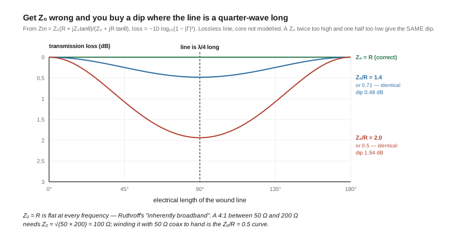
The practical consequences are concrete:
- A 1:1 choke works between 50 Ω and 50 Ω, so it wants
Z₀ = 50 Ω. Winding it with the feed coax itself is therefore exactly right, which is a happy accident of the most common construction. - A 4:1 working 200 Ω → 50 Ω wants
Z₀ = √(50 × 200) = 100 Ω. Not 50, not 75. This is why 4:1 Guanella baluns are wound with a bifilar pair spaced to give roughly 100 Ω rather than with coax. - A 9:1 working 450 Ω → 50 Ω wants
Z₀ = √(50 × 450) = 150 Ωper line. - A 49:1 working 2450 Ω → 50 Ω wants
Z₀ = √(50 × 2450) = 350 Ω, which is genuinely awkward to realise in a small winding and is one of the reasons the high-ratio end of the family leans on autotransformer construction instead (§10).
Note what this rule does not say. It says nothing about turns count, core material or power. It is a statement about the geometry of the wire pair, and it is orthogonal to everything Vol 3 discusses. A transformer can have an ideal core and the wrong Z₀, in which case it will be lossless at low frequency and dip mid-band; or the right Z₀ and the wrong core, in which case it will be flat where it works and simply stop choking at the low end.
2.8 Guanella’s series-parallel ladder and the N² rule
Guanella’s combination rule is easier to derive than to remember, so it is worth deriving once.
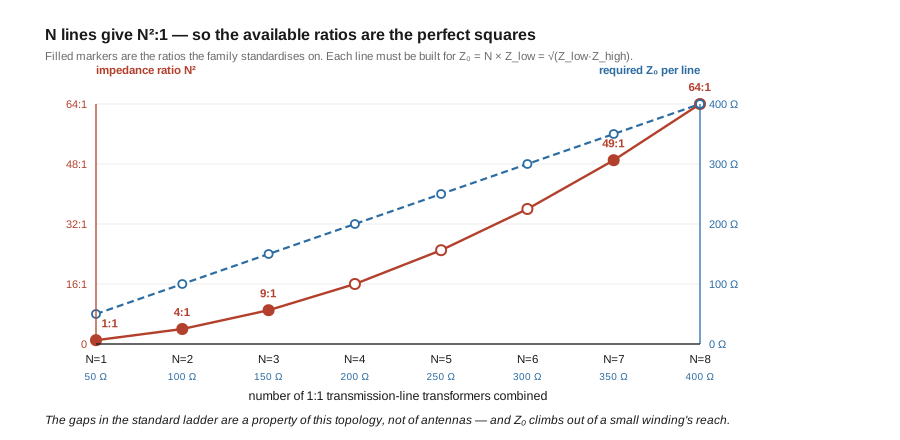
Take N identical 1:1 line transformers. Connect their inputs in parallel and their outputs in series. On the low-impedance side, the same voltage V appears across all N inputs and the source current I divides N ways, so each line’s input sees V / (I/N) = N · Z_low. On the high-impedance side, the N outputs are in series, so each carries the full current and one Nth of the total voltage — each line’s output sees Z_high / N.
Each line therefore works between N · Z_low and Z_high / N. For a well-behaved line those must be equal:
N · Z_low = Z_high / N ⟹ Z_high / Z_low = N²So N lines give an N² impedance ratio — Guanella’s result. And the common value each line works between is N · Z_low = √(Z_low · Z_high), which is §7’s condition again, arrived at independently. The two rules are the same rule.
Table 2 — 8. Guanella's series-parallel ladder and the N² rule
| Lines N | Ratio N² | Each line works between | Required Z₀ (50 Ω low side) |
|---|---|---|---|
| 1 | 1:1 | 50 Ω ↔ 50 Ω | 50 Ω |
| 2 | 4:1 | 100 Ω ↔ 100 Ω | 100 Ω |
| 3 | 9:1 | 150 Ω ↔ 150 Ω | 150 Ω |
| 4 | 16:1 | 200 Ω ↔ 200 Ω | 200 Ω |
| 7 | 49:1 | 350 Ω ↔ 350 Ω | 350 Ω |
Two things this table makes obvious. First, the ratios available from this construction are perfect squares only — 1, 4, 9, 16, 25, 36, 49, 64. That is the reason the standard ratio ladder in Vol 1 §9 has the gaps it does; the gaps are a property of the topology, not of the antennas. Second, the required Z₀ climbs linearly with N while the practical range of a wound pair does not, which is what makes the high-ratio end of the ladder hard to build as a true Guanella.
2.9 Bandwidth — what sets each end
A transmission-line transformer’s passband is bounded at both ends, by two unrelated mechanisms pulling the turns count in opposite directions.
The low end is set by the choking inductance. Ruthroff: “the low frequency response is determined in the usual way, i.e., by the primary inductance. The larger the core permeability, the fewer the turns required for a given low frequency response and the larger the over-all bandwidth. Thus a good core material is desirable.” Below the frequency where the wound assembly’s reactance is large compared with the impedances it works between, the core stops isolating and the device stops behaving as a transformer. More turns and more permeability push this limit down.
The high end is set by the length of the winding. As §5 and §7 established, the wound line is a real transmission line with real delay; once its length is a significant fraction of a wavelength, phase errors and the quarter-wave dip appear. Fewer turns and shorter wire push this limit up.
More turns for the low end, fewer for the high end. Every design in Vol 5 is a choice on that axis.
There is a third factor that makes the trade less painful than it looks, and Ruthroff identifies it in a passage that is really about complex permeability — the subject of Vol 3:
“The permeability of some ferrites is very high at low frequencies and falls off at higher frequencies. Thus, at low frequencies, large reactance can be obtained with few turns. When the permeability falls off the reactance is maintained by the increase in frequency and good response is obtained over a large frequency range.”
Read that carefully, because it is the key to why ferrite works at all here. Reactance goes as μ × f. Permeability falls with frequency; frequency rises. The two effects partially cancel, and the choking reactance stays useful across a far wider range than either factor alone would allow. This is a feature of the falling permeability curve, not a defect to be engineered around — and it is why the “useful frequency range” of a mix is a genuinely meaningful published quantity rather than a marketing number.
He adds one condition that constrains construction: “It is important that the coupling be high at all frequencies or the transformer action fails. Fortunately, the bifilar winding tends to give good coupling.” Tight coupling is not optional, and it is another reason the wires are twisted together — the same choice that sets Z₀ in §6.
2.10 Autotransformers — the other topology
Everything so far has been transmission-line transformers. There is a second, older topology that the high-ratio end of the family actually uses, and it deserves an honest account rather than being treated as the inferior option.
An autotransformer is a single tapped winding. The impedance ratio comes from the square of the turns ratio between the tap and the winding’s full length, exactly as in a conventional transformer, and there is a galvanic connection between input and output by construction.
Its properties, against a TLT:
- Narrower bandwidth. There is no
Z₀to arrange, so there is no mechanism enlisting the interwinding capacitance; the conventional resonance of §6 applies. - Higher loss, because it relies on ordinary transformer action through the core, so the core’s loss is in the signal path rather than only in the common-mode path.
- No isolation. It cannot be a current balun.
- Far easier to build at extreme ratios, and this is the decisive point. A 49:1 Guanella needs seven lines of 350 Ω; a 49:1 autotransformer needs one wire, two taps, and sixteen turns.
For an unun, the lack of isolation costs nothing, because Vol 1 §8 established that an unun has nothing to isolate — both sides are single-ended. So the trade at the top of the ladder is bandwidth and loss against buildability, in an application where isolation was never on the table. That is why the standard EFHW transformer is an autotransformer and not a seven-line Guanella, and it is a sound engineering choice rather than a compromise.
The consequence, which Vol 4 develops, is that an end-fed installation typically needs two devices doing two jobs: an autotransformer unun for the ratio, and a separate current choke for the balance. A single core cannot do both well at 49:1.
2.11 Which topology for which job
Table 3 — 11. Which topology for which job
| Job | Topology | Why |
|---|---|---|
| Feedpoint choke on any coax-fed antenna | Guanella 1:1 (current) | It is the choke. Z₀ = 50 Ω, so wind it with the feed coax. |
| Balanced feedpoint at 4:1 — OCFD, folded dipole | Guanella 4:1 (current), two lines at Z₀ = 100 Ω | Current-forcing against an asymmetric load; isolation retained. |
| 4:1 in a symmetric, low-Z circuit — inside a tuner | Ruthroff 4:1 acceptable | One core, one bifilar pair; asymmetry is not present to be mishandled. |
| 9:1 for a random wire | Guanella 9:1 (three lines at 150 Ω) or trifilar autotransformer | Unbalanced both sides, so isolation is not the criterion; a tuner finishes the match. |
| 49:1 / 64:1 for an EFHW | Autotransformer, plus a separate current choke | Seven lines of 350 Ω is impractical; the choke does the balance job separately. |
| Common-mode suppression only, nothing to transform | Bead string or wound 1:1 choke | No ratio wanted. Not a transformer at all. |
The single sentence version: when the antenna is balanced, use a current balun; when it is not, use whatever transforms the impedance and add a choke for the balance.
2.12 Where this volume hands off
- The
Z₀condition of §7 and the ladder of §8 say what geometry the wire needs. What the core needs — the complex permeability behind Ruthroff’s falling-μobservation in §9, the mix-by-mix data, and why a choke is a resistor at HF rather than an inductor — is Vol 3. - The ratios as built objects, the corrected 49:1 autotransformer arithmetic, and the compensation capacitor: Vol 4.
- Turns counts,
Z₀in practice, and measuring a finished device: Vol 5. - The common-mode problem these topologies exist to solve, and the resistive-versus-reactive criterion that judges them: Vol 1.
Outward: Antenna Tuners for the balanced-tuner alternative to a feedpoint balun, and NanoVNA for the S-parameter technique that measures a Z₀ error as the dip in §7.
2.13 Resources
- Guanella, G., “Novel matching systems for high frequencies”, Brown Boveri Review, September 1944, pp. 327–329. The origin of the transmission-line transformer and of the series-parallel N² combination rule. ⚠ Cited from secondary sources; the paper itself was not read in this pass — unlike Ruthroff’s below, which was. That matters little here because §8 derives the N² rule from first principles rather than quoting it, so the result does not depend on the citation; but the page numbers should be checked before being relied on.
- Ruthroff, C. L., “Some Broad-Band Transformers”, Proceedings of the IRE, August 1959, pp. 1337–1342. Bell Telephone Laboratories, Holmdel NJ; manuscript received 5 February 1959, revised 1 April 1959. Source of every quotation in §§1, 4, 5, 6, 7 and 9, of the
Z₀ = 2R_gcondition labelled in his Fig. 4, and of the 20,000:1 bandwidth-ratio claim. Cores for his experimental transformers were supplied by F. J. Schnettler of Bell Telephone Laboratories. - Sevick, J. (W2FMI), Understanding, Building, and Using Baluns and Ununs: Theory and Practical Designs for the Experimenter. The practical companion to his Transmission Line Transformers; the standard modern working-through of the Guanella and Ruthroff families. ⚠ Note the title — the seed material for this dive cited it as “Building and Using Baluns and Ununs”, dropping the leading word.
- Trask, C. (N7ZWY), “A Tutorial on Transmission Line Transformers.” A modern tutorial treatment that traces the Guanella and Ruthroff lineages and their combination rules.
- Hunt, S. E. (G3TXQ), “Common-mode chokes.” The measured basis for judging any of these topologies as a choke rather than as a transformer — see Vol 1 §6.
Comments (0)