BALUNs & UNUNs · Volume 3
Ferrite — Complex Permeability, Choking Impedance, Loss and Saturation
Why a wound ferrite core is a resistor at HF and an inductor below it, derived from the complex permeability; the choking impedance of N turns on a given core from first principles; the mixes as their manufacturer actually specifies them; what G3TXQ's measurements say about turns, stacking, and where each mix peaks; why core loss rather than saturation is the usual power limit; duty cycle as a thermal question; and how to identify an unmarked core — including the colour-code myth
3.1 About this volume
Vol 1 established that a choke has to present a high and resistive impedance to the common mode, and that a merely reactive choke of a few hundred ohms can make matters worse. Vol 2 established what geometry the wire needs. Neither said anything about which lump of ferrite to buy, and that is this volume.
The reason a whole volume goes to the material is that “resistive” is not a property you can arrange by winding. It comes from the core, it is strongly frequency-dependent, and the quantity that governs it — the imaginary part of the permeability — is not the number printed at the top of the datasheet. An operator who selects a mix by initial permeability, which is the obvious thing to do, will select the wrong one about as often as the right one.
So this volume derives the choking impedance from the complex permeability, shows why the resistive term takes over at HF, and only then goes to the mixes. That order matters: with the derivation in hand, the manufacturer’s own frequency ranges and the published measurements both become readable, and the contradiction the seed material for this dive carried — and which the hub inherited — resolves cleanly.
3.2 Complex permeability — μ′ and μ″
A ferrite’s permeability is not a single number. It is complex, and conventionally written:
μ_r = μ′ − j μ″μ′ is the part that stores energy — it is what makes a wound core an inductor. μ″ is the part that dissipates it — it is what makes a wound core a resistor. Both vary with frequency, and they do not vary together.
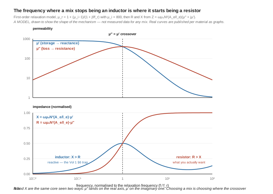
At low frequency μ′ equals the initial permeability μ_i that the datasheet quotes, and μ″ is small. As frequency rises, the magnetic domains can no longer follow the field; the material passes through a relaxation (in MnZn ferrites) or a ferrimagnetic resonance (in NiZn), and in that region μ′ collapses while μ″ rises to a broad peak. Above it, both fall.
The consequence is the single most important fact in ferrite selection: the frequency where a mix stops being a good inductor is the frequency where it starts being a good resistor. The datasheet’s “useful frequency range” for suppression is naming that second region, not the first, which is why the number looks wrong to anyone reading it as an inductor spec.
Ruthroff saw the useful half of this in 1959 and stated it in terms of reactance, before the language of complex permeability was standard in this literature:
“The permeability of some ferrites is very high at low frequencies and falls off at higher frequencies. Thus, at low frequencies, large reactance can be obtained with few turns. When the permeability falls off the reactance is maintained by the increase in frequency and good response is obtained over a large frequency range.”
Reactance goes as μ′ × f. μ′ falls, f rises, and the product stays useful across a far wider span than either term alone would give. Ruthroff was describing why a transformer works over decades; the same cancellation is why a choke does.
3.3 The choking impedance of a wound core, derived
The choking impedance follows from the complex permeability in three steps and no hand-waving.
For N turns on a toroid of effective cross-section A_e and effective magnetic path length l_e, the inductance is:
L = μ₀ μ_r N² A_e / l_eThe impedance of an inductor is Z = jωL. Substituting the complex permeability μ_r = μ′ − jμ″:
    Z  =  jω μ₀ N² (A_e / l_e) (μ′ − j μ″)

       =  ω μ₀ N² (A_e / l_e) · (μ″  +  j μ′)
Which separates into resistance and reactance:
    R  =  ω μ₀ N² (A_e / l_e) · μ″          the DISSIPATIVE part
    X  =  ω μ₀ N² (A_e / l_e) · μ′          the REACTIVE part
Read those two lines carefully, because between them they explain almost everything practical about chokes:
μ″ is the resistance and μ′ is the reactance. The −j in the permeability and the +j in jωL multiply to move the loss term onto the real axis. So the “lossy” part of a ferrite is not a defect to be minimised in a choke — it is the choke. This is the exact opposite of the design goal in a tuned inductor, and it is why a mix chosen for a good inductor makes a poor choke and vice versa.
Both terms scale as N². Doubling the turns quadruples both R and X — at a given frequency. But μ′ and μ″ are themselves functions of frequency, so more turns also drags the whole curve down the frequency axis, which is why §6’s measured charts show the peak moving with turn count rather than just growing.
Both scale with A_e/l_e, which is a pure geometry factor. Stacking two identical cores doubles A_e with l_e unchanged, so it doubles both terms — without touching the frequency dependence. That is the mechanism behind the stacking rule in §6, and it is why stacking and adding turns are not interchangeable even when they raise the impedance by the same factor at one spot frequency.
3.4 Why a choke becomes a resistor, and why that is what you want
Putting §3 together with Vol 1 §6 closes the loop that the seed material left open.
G3TXQ’s design rule was: “Aim to choose a choke which has a high impedance and is Resistive over the frequency range of interest,” and his charts mark the resistive region separately with the criterion Rs > |Xs|. From §3, that criterion is simply:
R > X ⟺ μ″ > μ′The resistive region of a choke is the region where the material’s loss term exceeds its storage term. It is not an incidental property of a particular winding; it is a property of the mix, and it is the region the manufacturer’s suppression rating is describing.
That is also why the two failure modes of a badly chosen choke look so different:
- Too low in frequency for the mix —
μ′still dominates, so the choke is an inductor. Its impedance may be a respectable number, but it is reactance, and reactance can cancel against the common-mode path’s own reactance and increase the braid current. This is the 0.17 A → 0.64 A trap of Vol 1 §6. - Too high in frequency for the mix — both terms have fallen, the impedance is simply small, and the choke does nothing. Harmless but useless.
The first failure is worse than having no choke. The second is merely a waste. Both are avoided by the same act: match the mix’s resistive region to the bands you use.
3.5 The mixes, from the manufacturer’s own data
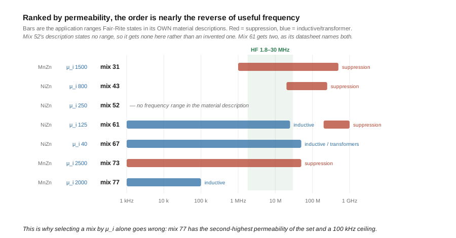
Fair-Rite’s mix numbering is the industry reference. The table below gives the published initial permeability and, verbatim, the application range the manufacturer itself states — because §2 established that a mix’s suppression range and its inductive range are different regions of the same curve, and quoting the manufacturer avoids inventing a single “useful range” that conflates them.
Table 1 — 5. The mixes, from the manufacturer's own data
| Mix | Type | μ_i | Fair-Rite’s own stated application, quoted |
|---|---|---|---|
| 31 | MnZn | 1500 | ”designed specifically for EMI suppression applications from as low as 1 MHz up to 500 MHz” |
| 43 | NiZn | 800 | ”our most popular ferrite for suppression of conducted EMI from 20 MHz to 250 MHz. This material is also used for inductive applications such as high frequency common-mode chokes” |
| 52 | NiZn | 250 | ”a new high frequency NiZn ferrite material that combines a high saturation flux density and a high Curie temperature” (no frequency range given in the material description) |
| 61 | NiZn | 125 | ”developed for a range of inductive applications up to 25 MHz. This material is also used in EMI applications for suppression of noise frequencies above 200 MHz” |
| 67 | NiZn | 40 | ”intended for broadband transformers. Antennas and Hi Q inductor applications up 50MHz” |
| 73 | MnZn | 2500 | ”supplied only in small cores to suppress conducted EMI frequencies below 50 MHz” |
| 77 | MnZn | 2000 | ”for use in a wide range of high and low flux density inductive designs for frequencies up to 100 kHz” |
Four things worth drawing out, because each corrects something commonly said.
Mix 61 is listed twice, for two different things. “Inductive applications up to 25 MHz” and “suppression above 200 MHz” are the two sides of §2’s curve — the same material, below and above its transition. Anyone quoting a single range for mix 61 has picked one and dropped the other.
Mix 67 is a transformer material, not a UHF choke material. Its own description says “broadband transformers. Antennas and Hi Q inductor applications up 50MHz”. Low μ_i, low loss — the properties you want in an inductor and precisely the wrong ones in a choke. The seed material for this dive filed mix 67 under “UHF chokes, microwave, 30–1000 MHz”, which is not what the manufacturer says it is for.
The mix-77 warning is right in direction and an order of magnitude short. The seed says mix 77 “saturates badly above ~1 MHz”. Fair-Rite’s own ceiling is 100 kHz — ten times lower. If anything the cheap-eBay-UNUN warning that follows from it should be stronger than the seed makes it, not weaker. (Mix 77 is a power-transformer material; there is nothing wrong with it in a switching supply.)
Mix 73 has the highest permeability of the set at 2500 and is “supplied only in small cores… below 50 MHz” — which is exactly the profile of a bead you slide over coax, and is worth remembering when Vol 5 gets to bead-string chokes.
3.6 What the measurements say — turns, stacking, and where each mix peaks
Datasheet ranges tell you about the material. They do not tell you what 12 turns on a 2.4-inch core will actually do at 7 MHz. For that there is one widely-used body of measurement: G3TXQ’s per-mix choke charts, four plots (types #31, #43, #52 and #61, each last updated 4 December 2017) measured by the series-through S21 method Vol 5 documents.
What he measured, literally: 5, 9, 12 and 17 turns of RG58 on 1×, 2× and 4× stacked “240-size” toroids in each of mixes 31, 43, 52 and 61 (plus an 11-turn row on 2×FT240-52). Each chart runs 0–30 MHz, colours the impedance in bands of >500 Ω, >1 kΩ, >2 kΩ, >4 kΩ and >8 kΩ, and marks separately, with a black bar, the span over which the impedance is predominantly resistive (Rs > |Xs|) — the criterion §4 derived.
⚠ A deliberate restraint about these charts. They are bitmap plots roughly 670 pixels wide. Reading a band edge off one to a tenth of a megahertz and printing it as a measured value would be inventing precision the source does not carry — the specific failure this project has been bitten by before, where interpolated figures landed close enough to the truth that every downstream check passed. So what follows are the conclusions that survive a reading error of a megahertz or two, because they are gross features of the plots. For a specific turns-and-core combination, read his charts.
Three findings, in increasing order of usefulness:
Adding turns moves the peak DOWN in frequency. On any one mix and core count, the 5-turn row’s best impedance sits at the top of the chart and the 17-turn row’s sits at the bottom. §3 predicts exactly this: N² multiplies both R and X, but the winding’s own self-capacitance and the material’s falling permeability put the assembly’s best region lower as the turns rise. So turns are not a volume knob — they are a tuning knob, and the question is never “how many turns is best” but “how many turns puts the resistive peak on my bands”.
Stacking cores raises the impedance without moving the peak much. Nine turns on four stacked FT240-43 cores holds a top-band impedance across a far wider span than nine turns on one core. §3 predicts this too: stacking multiplies A_e and leaves the frequency dependence alone. This is the knob to reach for when the peak is in the right place but the magnitude is short — and it is why the high-power chokes in Vol 5 are stacks rather than heavier windings.
Each mix’s best region sits at a different place on the chart, and the order is 31, then 43, then 52. At a comparable turns count on a single core, mix 31’s high-impedance region sits toward the low-HF end of the plot, mix 43’s sits mid-HF, and mix 52’s higher still. Mix 31’s resistive bars also begin lowest in frequency, which by §4 matters more than the magnitude does. Mix 61’s chart is consistent with its datasheet’s VHF orientation.
3.7 Resolving the mix-31-versus-43 question
This dive inherited a contradiction, and it is worth naming plainly because the hub has been publishing both sides of it.
The seed material for this volume made mix 43 the “HF workhorse” with a useful range of “1–50 MHz”, and filed mix 31 as a narrow “1–15 MHz” part. But Single-Band Dipoles Vol 2 says the opposite — mix 31 for low-to-mid HF, mix 43 for upper HF and VHF. Two volumes on the same site, disagreeing about the most common component in the whole hub.
Both independent sources point the same way, and it is not the seed’s:
- The manufacturer. Fair-Rite specifies mix 31 for suppression “from as low as 1 MHz”, and mix 43 for suppression “from 20 MHz to 250 MHz”. If you want a choke that is doing its job on 160 m and 80 m, the manufacturer’s own indicated part is 31, not 43.
- The measurements. §6’s charts put mix 31’s high-impedance and resistive regions lowest in frequency of the three HF-relevant mixes.
So the practical guidance, and the correction this volume makes:
Table 2 — So the practical guidance, and the correction this volume makes
| Bands | Mix | Why |
|---|---|---|
| 160 m, 80 m, 40 m | 31 | Its resistive region reaches lowest; the mix the manufacturer specifies from 1 MHz |
| 40 m through 10 m | 43 | The mid-HF workhorse, and genuinely so — just not down at 1.8 MHz |
| 10 m, 6 m, low VHF | 52 | Best region sits highest of the three |
| VHF / UHF | 61 | ”Suppression of noise frequencies above 200 MHz” |
⚠ And now the over-correction check, because this is exactly where one would slip. None of the above makes mix 43 a poor choice, and it would be wrong to read it that way. Fair-Rite explicitly names 43 for “inductive applications such as high frequency common-mode chokes”; it is the most-used ferrite in amateur baluns; and an FT240-43 choke on 20 m is a good choke. Two narrower statements are what the evidence supports: a 43 choke gives up its low-band performance first, and a single mix does not cover 1.8–30 MHz well — which is why a genuinely all-band installation either stacks cores, uses a mix-31 choke, or accepts that 160 m is the weak end. The seed’s error is the flat claim of a “1–50 MHz workhorse”, not the choice of 43 as such.
3.8 Loss and heating — why saturation is usually the wrong worry
Ask why a balun failed and the usual answer is “the core saturated”. Usually it did not.
§3 gives the reason. The choke’s resistance is real:
R = ω μ₀ N² (A_e / l_e) · μ″and any common-mode current flowing through it dissipates I²R in the core, as heat. That is not a fault condition — it is the mechanism working as designed. A resistive choke absorbs the common-mode power it is suppressing, and the power has to go somewhere.
This has two consequences that the seed material’s power tables obscure:
The power limit of a choke is thermal, not magnetic. The core has a Curie temperature, above which it stops being ferrimagnetic; permeability collapses, the choking action disappears, and — because the impedance falls — the current rises. It is a runaway. What sets the rating is how much heat the core can shed, which is a function of surface area, enclosure, and airflow, not of the flux density.
A choke that is doing more work gets hotter. This is genuinely counterintuitive: the better your choke is at absorbing common-mode current, the more of that current’s power it converts to heat. G3TXQ makes the point directly: “Resistive chokes have the disadvantage that if they have insufficient impedance to reduce the CM current to a very low value, there may be significant core heating.” The way out is not a lossless choke — it is enough impedance that the current becomes small, because dissipation goes as I². Halving the common-mode current quarters the heating. An undersized resistive choke is the worst thermal case: enough loss to dissipate, not enough impedance to stop the current.
Saturation is a real phenomenon, and it belongs to the differential path of an impedance-transforming device carrying full transmitter power at low frequency — a 49:1 unun on 160 m at a kilowatt, not a 1:1 choke. Mix 52 exists partly for this: its own datasheet advertises “a high saturation flux density and a high Curie temperature”, which are the two properties that matter for a hot, hard-worked transformer core. Vol 4 picks this up where it belongs, with the high-ratio ununs.
3.9 Duty cycle is a thermal question, not a power derating
Since §8 established that the limit is heat, duty cycle needs restating, because the seed material’s table treats it as a power derating and that gets the modern digital modes wrong.
A rating quoted for SSB assumes speech: brief peaks, a low average, and long gaps. The core’s temperature follows the average power over its thermal time constant, which for a 2.4-inch toroid in an enclosure is tens of seconds. So the right question is never “what fraction of a cycle is the transmitter on” but “what is the mean power over the next minute”.
That distinction is what the seed’s treatment of FT8 misses. It lists FT8 at “50% duty” with a “0.6–0.8×” power multiplier. But an FT8 transmission is a constant-envelope carrier at full power for most of its slot, then silence for the rest. The core sees full key-down heating, then a rest of comparable length. It is not a 0.6× power problem; it is a repeated thermal pulse, and whether it matters depends entirely on whether the transmission is short compared with the core’s thermal time constant. For a 15-second cycle and a large core, largely yes — the core averages. For a small core, or a long RTTY transmission, no: it accumulates.
The honest guidance, then, is a rule rather than a table:
- Speech and CW — the rating as quoted.
- Constant-carrier digital modes (FT8, FT4, RTTY, and AM or FM carrier) — treat the transmitter as running continuously at full power during a transmission and ask whether the core can shed that. Derate substantially, and use a larger core or a stack rather than a multiplier from a table.
- The real test is your hand. A choke that is warm after a contest is working and adequately sized. One that is too hot to hold is telling you the common-mode current is high — which is a pattern and noise problem as much as a thermal one, and points back at Vol 1 §7’s question of whether the impedance is high enough.
⚠ A caveat about the numbers in this area generally: published power ratings for baluns and chokes are rarely accompanied by the test conditions — ambient temperature, enclosure, airflow, duty, SWR at the device — that would make them comparable between vendors. Vol 5 treats a rating without stated conditions as a rough guide, not a specification.
3.10 Identifying an unmarked core — and the colour-code myth
You will accumulate unmarked cores. Since the mix decides everything in §§5–7, identifying them matters, and there is a widely-repeated shortcut here that does not work.
🔴 The myth: that ferrite mixes are identified by painted colour bands. The seed material for this dive states that “cores marked with a yellow or yellow-and-red painted band are Mix 77… cores marked with a black-and-gray band are typically Mix 43.” This conflates two different product families. Colour coding belongs to iron-powder cores, not ferrites — the Micrometals/Amidon iron-powder range is colour-coded by mix, which is why a T50-6 is yellow and a T50-2 is red. Ferrite toroids are not colour-coded, and an unpainted grey-black core tells you only that it is a ferrite.
That distinction is worth keeping for a second reason: iron powder and ferrite are not interchangeable and are easy to confuse by eye. Iron-powder mixes have very low permeability — mix 6 has μ_i of 8, against 800 for ferrite mix 43 — and are built for high-Q inductors, exactly the opposite of a choke. An iron-powder core wound as a common-mode choke will produce almost no choking impedance at all. If a “ferrite” core is painted, that is a signal it is probably not ferrite.
So identification has to be by measurement. The practical route, using the instrument this hub already covers:
- Wind a known number of turns — ten is convenient — and measure the impedance of the winding across HF with a NanoVNA. See NanoVNA Vol 4 for the measurement, and Vol 5 for the series-through fixture.
- Find where R overtakes X. By §4 that crossover is
μ″ = μ′, and it is characteristic of the mix. A crossover low in HF indicates a high-permeability MnZn material (31, 73, 77); one at upper HF or above indicates a lower-permeability NiZn (43, 52, 61). - Compute
μ_ifrom the low-frequency inductance using §3’s expression, if the core’s dimensions are known well enough to estimateA_e/l_e. That distinguishes 31 from 43 from 61 quickly, since their permeabilities differ by factors of two or more. - When it cannot be identified, do not use it for anything load-bearing. An unknown core in a 1:1 receive choke is a small risk. An unknown core in a 49:1 unun at a kilowatt is not.
3.11 Where this volume hands off
- The ratios as built objects — 1:1, 4:1, 9:1, 49:1 and 64:1 — the corrected EFHW autotransformer arithmetic, and the compensation capacitor: Vol 4. §8’s note that saturation belongs to the high-ratio transformer rather than to the choke is picked up there.
- BOMs, turns counts, and the series-through S21 fixture that measures
RandXseparately — the measurement this whole volume presumes, and which the seed material replaced with an SWR check that cannot see choking impedance at all: Vol 5. - The common-mode problem and the resistive-versus-reactive criterion this volume derives from
μ″ > μ′: Vol 1. - The
Z₀condition, which is orthogonal to everything here — a core choice cannot fix a wrong line impedance, and vice versa: Vol 2.
Outward: Single-Band Dipoles Vol 2, whose mix guidance §7 confirms and whose feedpoint choke is the commonest application of everything above; and NanoVNA Vol 4 for the measurement technique behind §10.
3.12 Resources
- Fair-Rite material data sheets (
31,43,52,61,67,73,77). Source of every initial-permeability figure and every quoted application range in §5. Quoted from the material descriptions verbatim; where a description states no frequency range, none is given here. - Hunt, S. E. (G3TXQ), “Common-mode chokes” — the per-mix charts for types #31, #43, #52 and #61, each last updated 4 December 2017, © G3TXQ. Configurations, impedance bands and the
Rs > |Xs|resistive criterion in §6 are read from those charts; per-combination band edges are deliberately not reproduced. The site’s certificate has lapsed since the author’s death; the charts are reachable through the Internet Archive. - Ruthroff, C. L., “Some Broad-Band Transformers”, Proc. IRE, August 1959, pp. 1337–1342. The falling-permeability passage quoted in §2.
- Micrometals / Amidon iron-powder core data. The colour-coded family §10 distinguishes from ferrite; mix 6 (
μ_i= 8, yellow) is the contrasting example. - Sevick, J. (W2FMI), Understanding, Building, and Using Baluns and Ununs. Core selection worked through for each ratio in the family.
Comments (0)