Antennas · Volume 33
Satellite Antennas & Rotators
Circular polarization, turnstiles, QFH, crossed Yagis, helices, dishes + LNBs, and az/el rotators — DIY build and commercial buy for every element that points an antenna at a moving (or geostationary) bird
33.1 About this volume
Every other volume in this series has assumed the other end of the link sits still. A repeater on a hilltop, a DX station across an ocean, a noise source down the block — the geometry is fixed and the only thing that moves is the operator’s patience. Satellites break that assumption. A low-earth-orbit bird crosses the whole visible sky in under fifteen minutes, climbing from one horizon to the other while its range, Doppler shift, and apparent polarization all slew continuously. A geostationary transponder sits dead still relative to your back yard but does so 35,786 km away, which sets its own brutal link budget. The antennas and the pointing hardware that cope with those two regimes are the subject of this volume.
This is the hardware half of the satellite cluster. Everything here is something you can hold, build, or bolt to a mast: the radiating element (turnstile, QFH, crossed Yagi, helix, dish), the pointing machinery (the az/el rotator), and the masthead glue (preamp, sequencer, LNB, bias-T, feedline). The software half — where the az/el numbers come from — lives in the companion Vol 34: two-body orbital mechanics, the six Keplerian elements, the TLE format and where it originates, SGP4/SDP4 propagation, the ECI→topocentric az/el/range transform, Doppler derivation, the tracking programs (Gpredict, SatPC32, Orbitron), and the three control paths (PC-driven via Hamlib/rotctld, a DIY K3NG/SatNOGS controller, and COTS controller boxes). When this volume says “the controller computes az/el and slews the rotator,” the how is Vol 34’s job; here we cover the rotator that the slew command lands on. QO-100 appears in both: the dish/LNB hardware is here, the “geostationary means no tracking” worked example is there.
The satellite classes in scope, and why each matters to a station that is already SDR-heavy:
Table 1 — The satellite classes in scope, and why each matters to a station that is already SDR-heavy
| Class | Representative birds | Band / mode | Hub radio that works it | TX? |
|---|---|---|---|---|
| Amateur LEO FM (“easy sats”) | SO-50, ISS cross-band, PO-101 | 2 m up / 70 cm down (V/U), FM | UV-K5 (HT, full-duplex-ish), any dual-band HT | Yes (Part 97) |
| Amateur LEO linear | RS-44, FO-29, JO-97 | V/U or U/V, SSB/CW linear transponder | HackRF One, an all-mode rig | Yes (Part 97) |
| Amateur GEO | QO-100 (Es’hail-2) NB transponder | 2.4 GHz up / 10.49 GHz down, SSB/CW/digital | HackRF (TX up), RTL-SDR (RX down via LNB) | Yes (Part 97), RX-only common |
| Weather — APT/LRPT | NOAA-15/18/19 (APT), Meteor-M N2-x (LRPT) | 137 MHz, FM/QPSK image telemetry | RTL-SDR — the canonical use | RX only |
| Weather — L-band | GOES-18/19 (HRIT), Himawari, Metop | ~1.69 GHz, digital | RTL-SDR + LNA, Airspy | RX only |
| L-band / other RX | Inmarsat/AERO, Iridium, GPS/GNSS | 1.5–1.6 GHz | RTL-SDR, HackRF | RX only |
| GEO comms / Starlink | broadcast GEO, Starlink user terminal | C/Ku/Ka | (situating note only) | n/a here |
Note: Amateur uplink to a satellite is transmitting, and every word of the series’ standard framing applies. You are operating under Part 97 on your authorized bands (the 2 m, 70 cm, 23 cm, and 13 cm amateur allocations carry the satellite sub-bands), and the same band plans, power limits, and station-identification rules hold as on any terrestrial contact — see Vol 31. The weather-sat, L-band, and GNSS reception in this volume is receive-only and gets ordinary framing. Nothing here authorizes transmitting on the 137 MHz weather-sat downlinks, the 1.6 GHz Inmarsat band, or any other non-amateur allocation.
33.2 Why satellites are different
The terrestrial antenna problem is “put the gain where the other station is and keep it there.” The satellite problem adds three complications that drive every design choice in this volume: the target moves (for LEO), the target is far and weak, and the polarization wanders.
33.2.1 The LEO pass — fast motion in two axes
A typical amateur or weather LEO orbits at 500–850 km altitude with an orbital period near 95–102 minutes. From the ground, a single usable pass lasts roughly 5 to 15 minutes from acquisition of signal (AOS) at one horizon to loss of signal (LOS) at the other. During that window the bird traces an arc across the sky dome, and your antenna — if it is a gain antenna — has to follow it in both azimuth and elevation.

Three features of that arc matter for hardware. First, azimuth and elevation both change continuously, and the rate is geometry-dependent: a low pass (peak elevation under 30°) crawls along near the horizon and is easy to track, while a high pass that climbs toward the zenith sweeps fast. Second, maximum elevation sets the link quality — a 75° pass puts the bird nearly overhead with minimal slant range and atmosphere, a 12° pass keeps it at the noisy, multipath-ridden horizon for the whole pass. Third, and most viciously, the zenith keyhole: on a pass that culminates near 90° elevation, the azimuth bearing swings through nearly 180° in a few seconds right at the top of the arc. No conventional az rotator slews that fast, so the array drops off the bird at the exact moment the signal is strongest. The standard mitigations — flipping the elevation past 90° so azimuth can stay put, or leading/lagging azimuth through the keyhole — are tracking-software behaviors covered in Vol 34; the hardware consequence is simply that you size the az rotator’s slew rate with the keyhole in mind, and you accept that an omnidirectional antenna sidesteps the whole problem.
33.2.2 Doppler, in preview
Because the bird is moving toward you on the rise and away on the set, its downlink frequency is shifted by the range-rate. At 70 cm (435 MHz) the total swing across a high pass is roughly ±10 kHz; at 2 m it is about ±3 kHz; at 23 cm it is several tens of kHz; at the 10 GHz QO-100 downlink the LNB’s own LO drift dwarfs the (zero, for GEO) satellite Doppler. This is a tuning problem, not an antenna problem, so the full derivation, the V/U-versus-U/V sign conventions, and the closed-loop CAT correction all live in Vol 34. It matters here only as a reminder that an FM “easy sat” tolerates the drift with its wide channel, while an SSB linear bird needs continuous retuning to stay intelligible — which is one more reason the FM birds are the beginner’s entry point and the linear birds reward an automated station.
33.2.3 Faraday rotation, spin fading, and the case for circular polarization
A linearly polarized wave passing through the ionosphere has its polarization plane rotated by the Faraday effect, by an amount that depends on frequency, path length, electron density, and the geomagnetic field — i.e. by an amount that is unpredictable and time-varying on a satellite path. Layer on top of that the satellite’s own tumble or spin (many cubesats and older birds are not three-axis stabilized), which rotates the spacecraft antenna relative to yours, and a ground station using a linearly polarized antenna sees deep, fast polarization fading: the received signal can drop 20+ dB and recover several times per minute as the incoming polarization sweeps through orthogonality with your antenna.
The fix is circular polarization (CP). A circularly polarized antenna responds to a rotating E-field at constant amplitude regardless of the instantaneous tilt angle, so Faraday rotation and spin fading become near-invisible. This is why almost every purpose-built satellite antenna in this volume is circularly polarized — turnstiles, QFHs, helices, and crossed Yagis all exist to produce CP. The cost is a fixed ~3 dB penalty whenever a CP antenna works a linearly polarized signal (or vice versa), and a 20+ dB penalty if you get the sense (RHCP vs LHCP) wrong, both covered in the next section.
33.2.4 The link budget — why a masthead preamp and good feedline are near-mandatory
Satellite downlinks are power-starved. A LEO cubesat transmits a few hundred milliwatts to a few watts through a low-gain antenna across hundreds of kilometers of slant range; QO-100’s narrowband transponder shares a modest EIRP across the whole footprint. Run the Friis equation for any of these and the received power lands somewhere in the −110 to −135 dBm range — close enough to the noise floor that every decibel of system noise figure and feedline loss matters directly.
Two consequences. First, the low-noise amplifier belongs at the antenna, not at the rig. System noise figure is dominated by the first stage and the loss ahead of it; a preamp at the masthead sees the antenna’s signal before the feedline attenuates it, whereas a preamp at the shack amplifies signal and the accumulated feedline loss equally and does little good. The masthead-preamp / LNA design, the sequencing needed to protect it on transmit, and the bias-T that powers it up the coax are the subject of Vol 19, cross-referenced again under companion gear below. Second, feedline loss is brutal at VHF/UHF/L-band and gets worse with frequency: a run of RG-58 that is merely lossy at 28 MHz throws away most of a 1.7 GHz GOES signal before it reaches the radio. Coax selection and the loss-vs-frequency tables are Vol 5; the satellite-specific rule is “shortest possible run of the best coax you can afford, with the active gain ahead of it.” At 10 GHz the problem is so severe that the LNB is mounted at the dish feed and only a downconverted ~739 MHz IF travels the coax — there is no other way.
33.3 Polarization for satellites
33.3.1 Circular polarization, RHCP and LHCP
A circularly polarized wave is two orthogonal linear components of equal amplitude, 90° apart in time phase. The resultant E-vector traces a circle as the wave advances. If, looking along the direction of propagation (from behind the wave, watching it recede), the vector rotates clockwise, the wave is right-hand circularly polarized (RHCP); counter-clockwise is LHCP. (The IEEE convention — looking in the direction of propagation — is the one used throughout this volume; some optics texts use the opposite handedness convention, which is a perennial source of confusion.)
The practical rule is that handedness must match end to end with one twist for reflection. A direct path from a RHCP spacecraft antenna to your ground antenna wants a RHCP ground antenna. A signal that has bounced once off a conductive surface flips sense. Most amateur and weather satellites that specify a sense use RHCP; some use LHCP; many cubesats use linear or are deliberately agnostic. Getting the sense wrong on a CP-to-CP path costs 20+ dB — it is the single most expensive mistake in satellite antenna work, and it is invisible on a spec sheet because both senses “work,” just one of them 100× worse.
33.3.2 Axial ratio — the figure of merit
No real antenna produces perfect circular polarization everywhere. The quality of the circularity is the axial ratio (AR): the ratio of the major to the minor axis of the polarization ellipse the antenna actually radiates (or receives). In decibels,
AR(dB) = 20 · log₁₀(E_max / E_min)
AR = 0 dB is perfect circular (the ellipse is a circle). AR = ∞ dB is pure linear (the ellipse has collapsed to a line). A practical “good CP” antenna holds AR ≤ 3 dB over its main beam, and spec sheets quote the on-boresight axial ratio because that is the best the antenna ever does.

The crucial real-world point is that axial ratio degrades away from boresight. An antenna that is a clean 1 dB AR on-axis can be 6–10 dB AR at 45° off-axis — i.e. it is barely circular at the edges of its pattern. A “CP antenna” is therefore only well-polarized over a limited beam, narrower than its half-power beamwidth. For a fixed omni like a QFH this means the overhead region is cleanly CP while horizon signals arrive nearly linear; for a tracked dish it means keeping the bird centered in the main beam matters for polarization as well as gain.
33.3.3 The 3 dB CP↔linear penalty, and when linear is good enough
Whenever a circularly polarized antenna receives (or transmits to) a purely linearly polarized signal, exactly half the power couples regardless of the linear signal’s tilt angle — a fixed 3 dB loss. The same 3 dB applies to a linear antenna working a CP signal. This is not a defect; it is the unavoidable consequence of the polarization mismatch, and it is the reason CP is worth it: that fixed, predictable 3 dB is vastly preferable to a linear-to-linear path’s unpredictable 0-to-20+ dB Faraday/spin fading.
So when is linear “good enough”? The clearest case is 137 MHz weather reception with a wideband omni — NOAA APT and Meteor LRPT come down strong, the FM/QPSK formats are forgiving, and a simple linear V-dipole or a turnstile that has drifted from ideal CP still produces clean images. Many hobbyists run a plain crossed-dipole turnstile or even a dedicated linear “137 MHz V-dipole” and get excellent passes. The other case is any path where you cannot control or predict the sense — some operators deliberately run a switchable-sense feed (a relay or hybrid that flips RHCP↔LHCP) so they can pick whichever sense is peaking on a given bird, accepting the 3 dB on a linear bird as the price of never being caught 20 dB down on the wrong CP sense.
33.4 Fixed and omnidirectional antennas — no rotator needed
The first strategic decision in satellite work is whether to track the bird with a gain antenna on a rotator, or to flood the whole sky with a fixed CP antenna that has gain everywhere it needs it and no moving parts. The fixed approach trades absolute gain for radical simplicity: no rotator, no controller, no keyhole, no aiming. For weather reception and for casual FM-bird work it is often the right answer, and it is always the right first answer.
33.4.1 The turnstile
A turnstile is two half-wave dipoles crossed at 90° in space and fed 90° apart in time phase. The spatial quadrature plus the temporal quadrature add up to circular polarization broadside to the plane of the dipoles.

The classic phasing is a quarter-wavelength of 75 Ω line feeding the second dipole: an electrical 90° delay, with the 75 Ω impedance also acting as a √(50·100) transformer that helps match the two paralleled dipoles to 50 Ω. Reverse which dipole gets the delay (or swap ports on a hybrid) and the sense flips RHCP↔LHCP. A bare turnstile radiates CP both up and down (a two-sided pattern); add a reflecting screen about 0.3 λ below the dipoles and the pattern is pushed up into a broad upward hemisphere — the configuration you want for satellites, sometimes called a turnstile-reflector or “TR” array. The turnstile’s overhead gain is modest (a few dBic) and its axial ratio is good near zenith but degrades toward the horizon. It is mechanically the simplest CP satellite antenna and an excellent 137 MHz weather workhorse.
33.4.2 The eggbeater
An eggbeater replaces the turnstile’s straight dipoles with two crossed full-wave loops, again fed in phase quadrature. The loops give it a fatter low-elevation pattern than a flat turnstile, so it holds CP usefully closer to the horizon — valuable for catching a bird at AOS/LOS. M2’s “eggbeater” line (the EB-144 and EB-432) are the canonical commercial examples. The eggbeater is the antenna of choice when you want fixed, no-track, all-sky CP coverage for FM birds and are willing to accept that you are several dB down on what a tracked Yagi would deliver — the convenience of never touching it during a pass is the whole point.
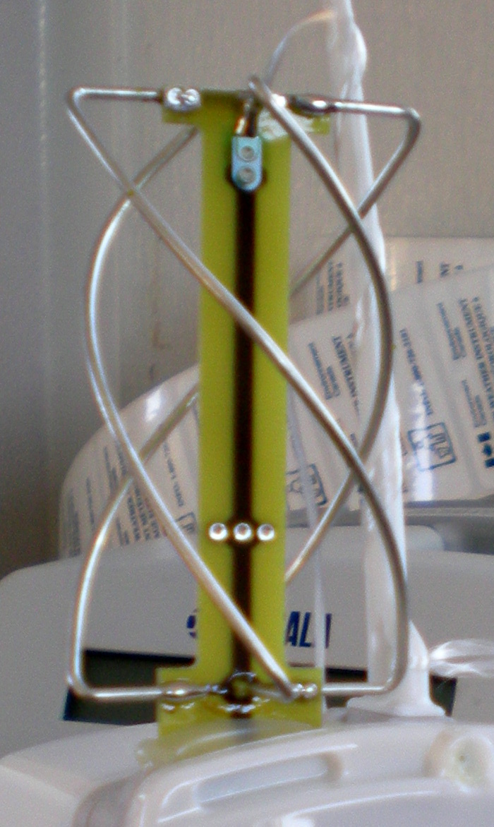
33.4.3 The quadrifilar helix (QFH) — the weather-sat workhorse
The QFH is the antenna most associated with reliable, unattended weather-satellite reception. It is two bifilar helical loops, mounted orthogonally, with one loop slightly larger (more inductive) and one slightly smaller (more capacitive) than resonance, so the two loops are self-phased ±45° to produce the 90° quadrature internally — no external phasing network at all.

The payoff is a beautifully broad, nearly hemispherical CP pattern with low axial ratio over most of the upper sky and a pattern that stays useful down to low elevations — exactly the shape you want for a LEO bird that you are not tracking, because it has near-uniform gain from horizon to horizon. There is no aiming, no rotator, and the cardioid-ish pattern even suppresses ground reflections somewhat. The penalty is mechanical: the helical geometry is fiddly to build accurately, and the dimensions are unforgiving (loop diameter ≈ 0.17 λ, axial length ≈ 0.42 λ for the larger loop, with the half-turn/full-turn winding setting the rest). The QFH is the headline DIY build of this volume.
33.4.4 Big wheel and Lindenblad — horizontal omni CP
Two less common fixed options round out the family. The big wheel is three half-wave loops arranged in a plane to give a horizontally polarized omnidirectional pattern (not CP, but omnidirectional gain at low elevation — useful for terrestrial horizontal-pol nets, occasionally pressed into satellite service). The Lindenblad is four dipoles tilted around a circle and fed in phase progression to produce a horizon-favoring CP omni pattern — historically a satellite-ground-station favorite (the AMSAT/Bruininga “PCB Lindenblad” made it buildable) precisely because its gain peaks toward the horizon where the bird spends most of its pass and is weakest, rather than toward the zenith where it is already close. Both are niche today next to the QFH and eggbeater but worth knowing when a specific pattern shape is wanted.
33.4.5 DIY build — a 137 MHz coaxial QFH for weather satellites
This is the canonical weather-sat antenna and one of the most satisfying afternoon builds in the series. Target: NOAA APT (137.1/137.9125/137.62 MHz) and Meteor-M LRPT (137.1/137.9 MHz), so center the design on ~137.5 MHz. The build below is the “coax-as-conductor” style, where the active loop is made from the coax itself and the feed is an infinite balun.
Geometry (RHCP, ~137.5 MHz). Use a published QFH calculator (John Coppens’ online QFH designer is the community standard — feed it 137.5 MHz, turns = 0.5, length-to-diameter ~0.4) and cut to its output. Representative dimensions land near:
Table 2 — Geometry (RHCP, ~137.5 MHz). Use a published QFH calculator (John Coppens' online QFH designer is the community standard — feed it 137.5 MHz, turns = 0.5, length-to-diameter ~0.4) and cut to its output. Representative dimensions land near
| Parameter | Larger (lower) loop | Smaller (upper) loop |
|---|---|---|
| Loop diameter | ~ 0.165 λ ≈ 360 mm | ~ 0.155 λ ≈ 340 mm |
| Axial length (height) | ~ 545 mm | ~ 515 mm |
| Half-turn twist | 180° over the height | 180° over the height |
| Conductor | RG-58 or copper tube/wire | same |
Cut to the calculator’s exact numbers for your center frequency; the ±1% sensitivity is real.
Bill of materials.
Table 3 — Bill of materials.
| Part | Spec | Source | Mid-2026 price |
|---|---|---|---|
| Support tube | 40 mm PVC or fiberglass, ~700 mm | hardware store | $8 |
| Spreader arms | PVC tee/cross fittings or 3D-printed jig | hardware / printed | $6 |
| Active-loop coax | RG-58 (or copper 1/4” tubing for rigid build), ~4 m | Mouser / DX Engineering | $10 |
| Feed/downlead coax | RG-58 or LMR-240, length to rig | Times Microwave | $15 |
| Common-mode choke | FT240-43 with ~8 turns, OR a coiled-coax balun | Vol 16 / Mouser | $12 |
| Connector | BNC or SMA to suit the RTL-SDR | Amazon / Mouser | $5 |
| Hardware | stainless screws, cable ties, sealant | hardware store | $8 |
| Total | ~$64 |
Construction. Drill the support tube for the four conductor exits at the calculated top and bottom positions for each loop, offset 90° around the tube. Form each helical conductor as a half-turn from bottom to top — the larger loop’s conductor is longer (lower resonance), the smaller loop’s is shorter. Join the loop tops to the feed: in the coaxial/infinite-balun style, the coax shield forms one half of the loops and the center conductor crosses at the top feedpoint; the downlead runs inside the support tube and exits at the base, where the choke kills common-mode current on the outside of the downlead (without the choke the feedline radiates and the pattern and AR are wrecked). Seal every penetration — this antenna lives outdoors for years.
Tuning. Sweep with a NanoVNA (Vol 24). A correct QFH shows a broad SWR dip below 1.5:1 across 136–138 MHz with no sharp resonance — the QFH is inherently broadband. If the dip is off frequency, the loops are mis-cut (the QFH has no trim screw; it is a cut-once design, so re-cut rather than fight it). Confirm the sense is RHCP if that is your target by checking that NOAA/Meteor passes peak rather than null; if every pass is weak, you likely built LHCP — swap the two loops’ roles or reverse the feed.
33.4.6 DIY build — a 137 MHz turnstile-reflector (the simpler alternative)
If the QFH’s helical geometry is more than you want to tackle, a turnstile is the easy CP weather antenna. Two 137 MHz half-wave dipoles (each leg ~520 mm of aluminum rod or wire) crossed at 90° on a small plate, fed with a quarter-wave of 75 Ω coax (RG-59, electrical length 0.25 λ × velocity factor ≈ 365 mm for solid-PE VF 0.66) bridging one dipole to the common feed, with a reflecting screen or four 137 MHz reflector rods ~0.3 λ (≈ 655 mm) below. BOM is essentially scrap aluminum, a junction box, a short RG-59 phasing line, and a 1:1 choke balun — under $30. It is a touch less omnidirectional and a touch worse in axial ratio than a good QFH but builds in an hour and works fine for APT/LRPT.
33.4.7 Commercial buys — fixed CP antennas (mid-2026)
Table 4 — Commercial buys — fixed CP antennas (mid-2026)
| Tier | Model | Type / band | Price | Notes |
|---|---|---|---|---|
| Budget | NooElec / generic 137 MHz V-dipole kit | linear V-dipole, 137 MHz | $25–35 | Linear, not CP, but excellent value for APT/LRPT RX; the default first weather antenna |
| Budget | RH-789 / generic 137 MHz QFH (import) | QFH, 137 MHz | $40–60 | Import QFHs vary; check the SWR sweep, some are mistuned |
| Mid | M2 Antenna EB-144 / EB-432 eggbeater | crossed-loop CP, 2 m / 70 cm | $130–160 each | The canonical fixed FM-bird antenna; no-track CP |
| Mid | Wimo / DIY-house QFH (137 MHz, assembled) | QFH, 137 MHz | $90–140 | A well-built QFH is worth it if you won’t DIY |
| Mid | M2 / Arrow turnstile (146/437) | crossed dipole + phasing | $90–120 | Simple CP, fixed mount |
| Premium | AMSAT-grade Lindenblad / custom QFH (137 / 1.7 GHz) | CP omni | $150–300+ | Specialist suppliers; L-band QFHs for GOES exist |
What to avoid: import “high-gain omni satellite” antennas claiming 8–9 dBi with no pattern or axial-ratio plot — a true omni cannot have high gain (gain is just pattern concentration, and an omni spreads it everywhere), and a CP antenna’s spec is meaningless without an AR figure. A linear 137 MHz V-dipole that honestly claims ~2 dBi is a better buy than a “9 dBi miracle omni.”
33.5 Tracked and directional antennas — need an az/el rotator
When you need more downlink margin than a fixed omni can give — to work a weak linear transponder, to decode marginal L-band weather, or to run reliable SSB through a LEO — you point gain at the bird and track it. The price is a rotator and a controller (Vol 34), or your own two arms for the handheld case.
33.5.1 Crossed Yagis with CP phasing — the classic V/U satellite array
The workhorse tracked satellite antenna is a pair of Yagis on a common boom, rotated 90° from each other, phased to produce CP. The Yagi theory — director/reflector geometry, boom-length-versus-gain, matching — is all in Vol 11; here the new element is the crossing and phasing that turns two linear Yagis into one CP array.

There are two ways to supply the 90° time phase. The quarter-wave line method co-locates both Yagis at the same boom positions and feeds one directly while the other gets an extra electrical quarter-wave of coax — simple, narrowband, and the sense is set by which Yagi gets the delay. The mechanical offset method feeds both Yagis in phase but slides one a quarter-wavelength forward along the boom, letting the spatial offset supply the quadrature. The premium approach is a 90° quadrature hybrid coupler (an ARR or similar polarization switch), which gives clean CP across the band and lets you switch RHCP↔LHCP with a relay — the right answer for a serious station that wants to chase whichever sense is peaking. A canonical amateur satellite array is a crossed 2 m Yagi (≈ 8–10 elements per plane) plus a crossed 70 cm Yagi (≈ 15–18 elements per plane) on a single cross-boom, both CP, mounted on one az/el rotator — this is what an M2 “LEO pack” is.
33.5.2 Handheld log-periodics — Arrow II and Elk, for walk-and-track FM birds
The simplest way to work an FM “easy sat” needs no rotator and no fixed install at all: a handheld dual-band beam that you aim by hand while you walk the bird across the sky. The two canonical antennas are the Arrow II 146/437 (a crossed… actually dual-band Yagi with separate 2 m and 70 cm element sets on one boom and an optional built-in duplexer) and the Elk 2M/440L5 (a dual-band log-periodic whose every element is active, giving smoother dual-band coverage in a lighter package). Both are linear by default — you rotate the whole antenna to follow the bird’s apparent polarization, manually compensating for Faraday rotation by twisting your wrist for the peak. With a dual-band HT like the UV-K5 (or a proper full-duplex satellite HT) you point, listen for your own downlink, and adjust — the classic “satellite in a backpack” station. This is the recommended entry point to satellite operating: a $130 antenna, an HT you already own, and a pass prediction from Vol 34’s software.
33.5.3 Axial-mode helix — natural CP for UHF, L-band, and as a dish feed
The axial-mode helix is the only antenna in this volume that produces circular polarization inherently, from a single feedpoint, with no phasing network — the geometry does it. Wind a conductor into a helix whose circumference is about one wavelength with a pitch of roughly 12–14° over a ground plane, and it radiates an end-fire CP beam whose sense follows the winding direction.

Gain scales with the number of turns (G ≈ 10.8 + 10·log₁₀(C²NS/λ³) dBi for N turns of spacing S), so a 10–16 turn helix gives a clean 12–15 dBic with a forgivingly broad beam and excellent axial ratio over that beam — broad enough that it tolerates the modest pointing error of a budget rotator. The handedness is set by the winding and cannot be changed without rewinding (you cannot relay-switch a helix’s sense), so build it to match your target bird’s sense. Helices shine at 70 cm and 23 cm as standalone tracked antennas, and at 13 cm / 10 GHz as dish feeds — a short helix at a parabola’s focus is one of the standard QO-100 feed options precisely because it delivers CP straight into the reflector.
33.5.4 Parabolic dish + feed + LNB — QO-100 downlink and GOES L-band
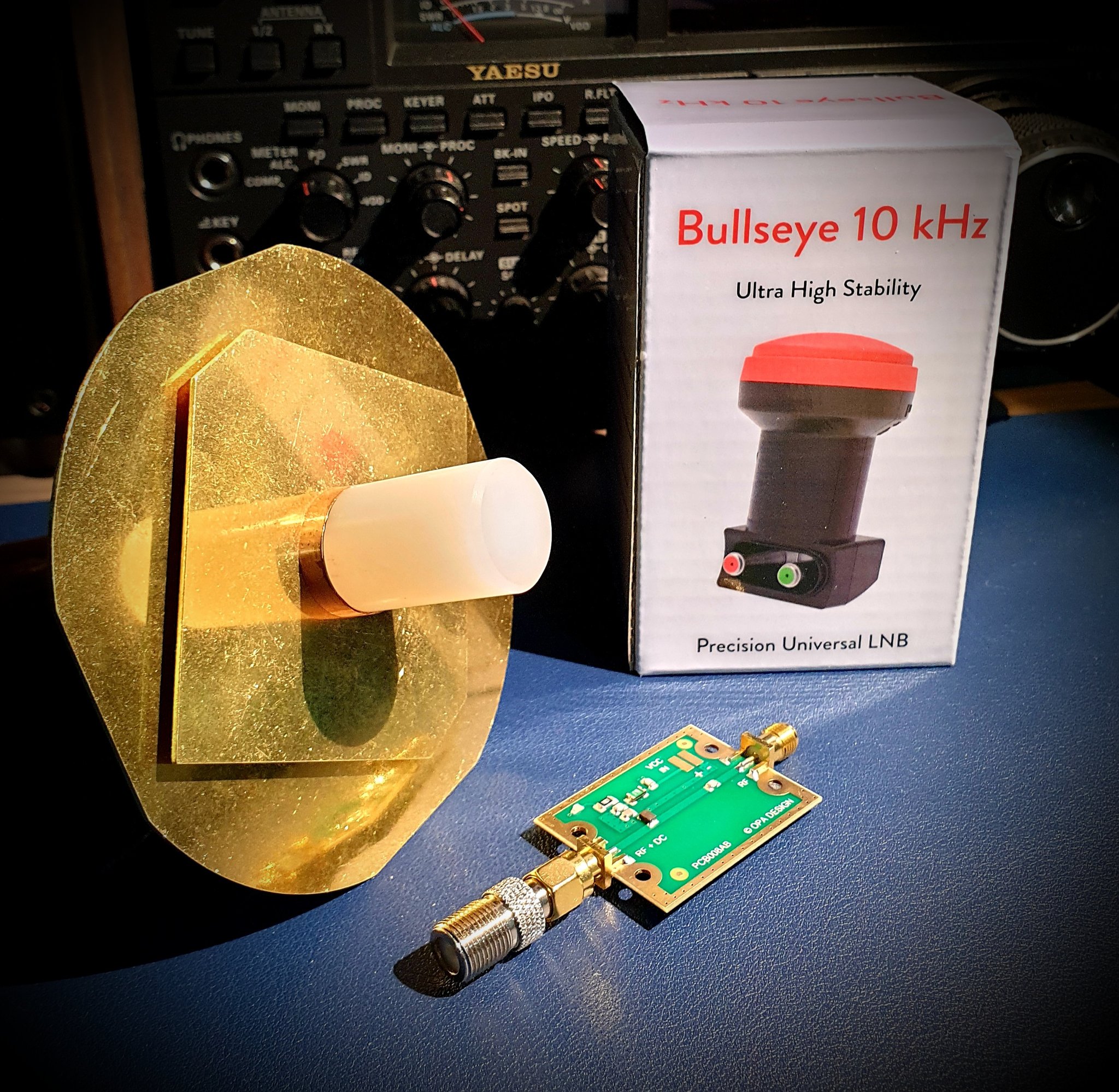
For the 10.489 GHz QO-100 narrowband downlink and for L-band weather (GOES HRIT ~1.69 GHz), the antenna is a parabolic dish with a feed at its focus and the active electronics mounted right there.

For QO-100 RX, the community-standard rig is almost comically cheap for what it does: a 60–100 cm offset dish (a recycled Ku-band TV dish is perfect) with a PLL LNB (a satellite-TV low-noise block-downconverter) at the focus. The LNB’s ~9.75 GHz local oscillator downconverts the 10.489 GHz signal to a ~739 MHz IF that an RTL-SDR or Airspy can digitize over ordinary coax. The LNB is DC-powered up the coax by a bias-T (12–14 V), which also passes the IF back down — one cable does both. The catch is LO stability: a stock TV LNB drifts tens of kHz, which is invisible for wideband TV but fatal for narrowband SSB/CW, so QO-100 operators either use a reference-locked LNB (the Bullseye 10 kHz LNB, or a PLL LNB modified to take an external 25/27 MHz GPSDO/OCXO reference) so the narrow signals stay put. Because QO-100 is geostationary, the dish is aimed once and bolted down — no rotator, no tracking (the worked example is in Vol 34).
For the QO-100 uplink (2.4 GHz, Part 97), the standard is a separate small dish or a helix/patch feed with a few watts driving a 2.4 GHz PA — many stations run a dual-feed prime-focus dish (RX LNB and TX feed sharing one reflector) or two co-pointed dishes. The TX side is a transmitting amplifier and antenna combination outside this volume’s antenna-geometry scope, but the dish and feed mechanics are identical to the RX case.
For GOES / Himawari L-band, the dish is smaller (a 1 m grid dish or even a large helix/patch works at 1.69 GHz) with a dedicated L-band LNA + filter right at the feed and the dish aimed once at the relevant geostationary GOES position (no tracking, like QO-100). This is one of the most rewarding RTL-SDR projects in the hub — full-disk Earth imagery from a back-yard dish.
33.5.5 L-band patch antennas — Inmarsat, Iridium, GNSS
For the broad-beam L-band RX cases — Inmarsat/AERO and STD-C around 1.54 GHz, Iridium around 1.62 GHz, and GPS/GNSS at 1.575 GHz (L1) — a small RHCP patch antenna is the right tool. These are all RHCP geostationary or wide-constellation signals coming from high in the sky with broad coverage, so a fixed patch (microstrip square or stacked patch) with a built-in LNA, aimed roughly up, captures them without any tracking. Active GPS patch antennas with integral LNAs are commodity parts (a few dollars), and purpose-built Inmarsat/Iridium patches with bias-T-fed LNAs are sold for exactly this hobby. The GNSS case gets only a note here: GPS/GNSS reception is a specialized RHCP-patch-plus-LNA problem with its own filtering needs, and the multi-radio “GPS exception” (its always-on, dedicated-antenna nature) is covered in Vol 30.
33.5.6 DIY build — a crossed 2 m / 70 cm satellite Yagi array
A buildable tracked array for the FM and linear birds: a crossed (CP) Yagi pair on one boom. This leans on the Vol 11 Yagi build for the per-element mechanics; the new work is crossing and phasing.
Design. Use a published satellite-Yagi design — the WA5VJB “Cheap Yagi” cross-boom designs and the DK7ZB crossed-Yagi notes are the community references — for a ~6-element 2 m and ~10-element 70 cm, each plane. Cut two identical Yagis per band, mount them 90° apart on a common boom (one set vertical-plane, one horizontal-plane), and phase each band’s pair for CP.
Bill of materials (per band, two Yagis).
Table 5 — Bill of materials (per band, two Yagis).
| Part | Spec | Source | Mid-2026 price |
|---|---|---|---|
| Element stock | 1/8”–3/16” aluminum welding rod or 1/2” tube | Texas Towers / hardware | $20 |
| Boom | 1” square aluminum, length per design | Texas Towers | $25 |
| Insulated element mounts | DX Engineering EMP or printed mounts | DX Engineering | $20 |
| Phasing line | RG-59 (75 Ω) or coax for electrical λ/4, OR ARR hybrid | Mouser / ARR | $10 / $90 |
| Power divider / combiner | 1/4-λ lines or commercial divider | Vol 18 | $15 |
| 1:1 choke balun | FT240-31, per plane | Vol 16 | $12 |
| Connectors, hardware, sealant | N or SMA, stainless | Mouser | $20 |
| Total (per band) | ~$120–200 |
Phasing. For the budget build, feed one Yagi of the pair directly and the other through an electrical quarter-wave of coax (length = 0.25 λ × cable velocity factor), combined to one feed; this sets a fixed CP sense. For switchable sense, replace the λ/4 line with an ARR-style 90° hybrid relay-switched coupler. Verify the sense on a known bird (peak, not null) and label it.
Tuning. Sweep each plane independently on the NanoVNA for SWR before combining; the crossing and phasing should not move resonance much, but the choke and combiner can. Mount the finished cross-boom on the az/el rotator with the boom balanced about the elevation axis.
33.5.7 Commercial buys — tracked satellite antennas (mid-2026)
Table 6 — Commercial buys — tracked satellite antennas (mid-2026)
| Tier | Model | Type / band | Price | Notes |
|---|---|---|---|---|
| Budget | Arrow II 146/437-10WBP (w/ duplexer) | handheld dual-band Yagi | $130–160 | The standard portable FM-bird antenna |
| Budget | Elk 2M/440L5 | handheld dual-band log-periodic | $130 | Lighter, smoother dual-band; linear |
| Budget | Recycled Ku offset dish + Bullseye LNB | QO-100 RX | $40 dish + $40 LNB | The cheapest path to a GEO transponder |
| Mid | M2 Antenna LEO-Pack (2MCP8A + 436CP16/30) | crossed Yagi CP set | $400–550 | The canonical fixed-station LEO array |
| Mid | WiMo / Diamond crossed Yagis | CP Yagi, 2 m / 70 cm | $200–400 | Per-band CP Yagis |
| Mid | Helix (commercial, 70 cm / 23 cm) | axial-mode CP | $120–250 | Standalone or dish feed |
| Premium | M2 Antenna 2MCP22 / 436CP42UG | high-gain crossed Yagi | $300–600 each | Big arrays for weak linear birds |
| Premium | QO-100 dual-feed dish + reference-locked LNB + 2.4 GHz uplink | GEO RX+TX station | $300–800 | Full QO-100 station with locked LO |
What to avoid: “satellite” Yagis sold without specifying CP sense or axial ratio (you cannot tell RHCP from LHCP from the listing, and sense is everything); generic 10 GHz LNBs for narrowband QO-100 work where LO drift will defeat SSB (buy reference-lockable or Bullseye); and dishes too small for the band (a 40 cm dish at 1.7 GHz has almost no gain — match dish size to wavelength).
33.6 Az/el rotators
A tracked array needs to move in two axes — azimuth across the compass and elevation up toward the zenith — and a plain terrestrial beam rotator gives you only the first. Elevation is the defining feature of a satellite rotator, and it is non-negotiable for any pass that climbs above ~30°: without it, the array is stuck pointing at the horizon while the bird is overhead.
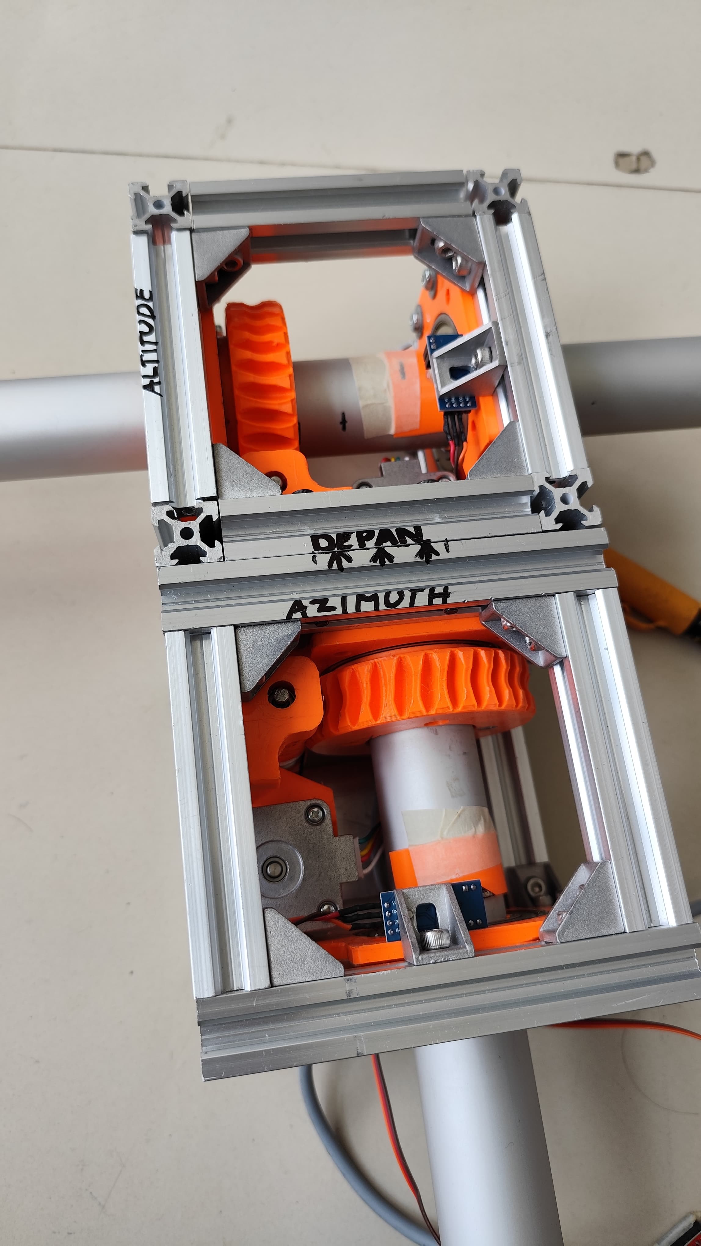
33.6.1 Anatomy

An az/el rotator is two independent gear trains stacked. The azimuth unit sits on the mast and rotates the whole assembly in the horizontal plane (typically 360°+ with some overlap to handle the keyhole). Above it, the elevation unit tilts the antenna boom from horizon (0°) up toward and sometimes past the zenith (the better units reach 180° so the array can “flip over” to dodge the keyhole). Each axis has its own motor and gear reduction, and — critically — its own position feedback sensor, because the controller must know where the array is pointing, not merely command it. Two sensor families dominate:
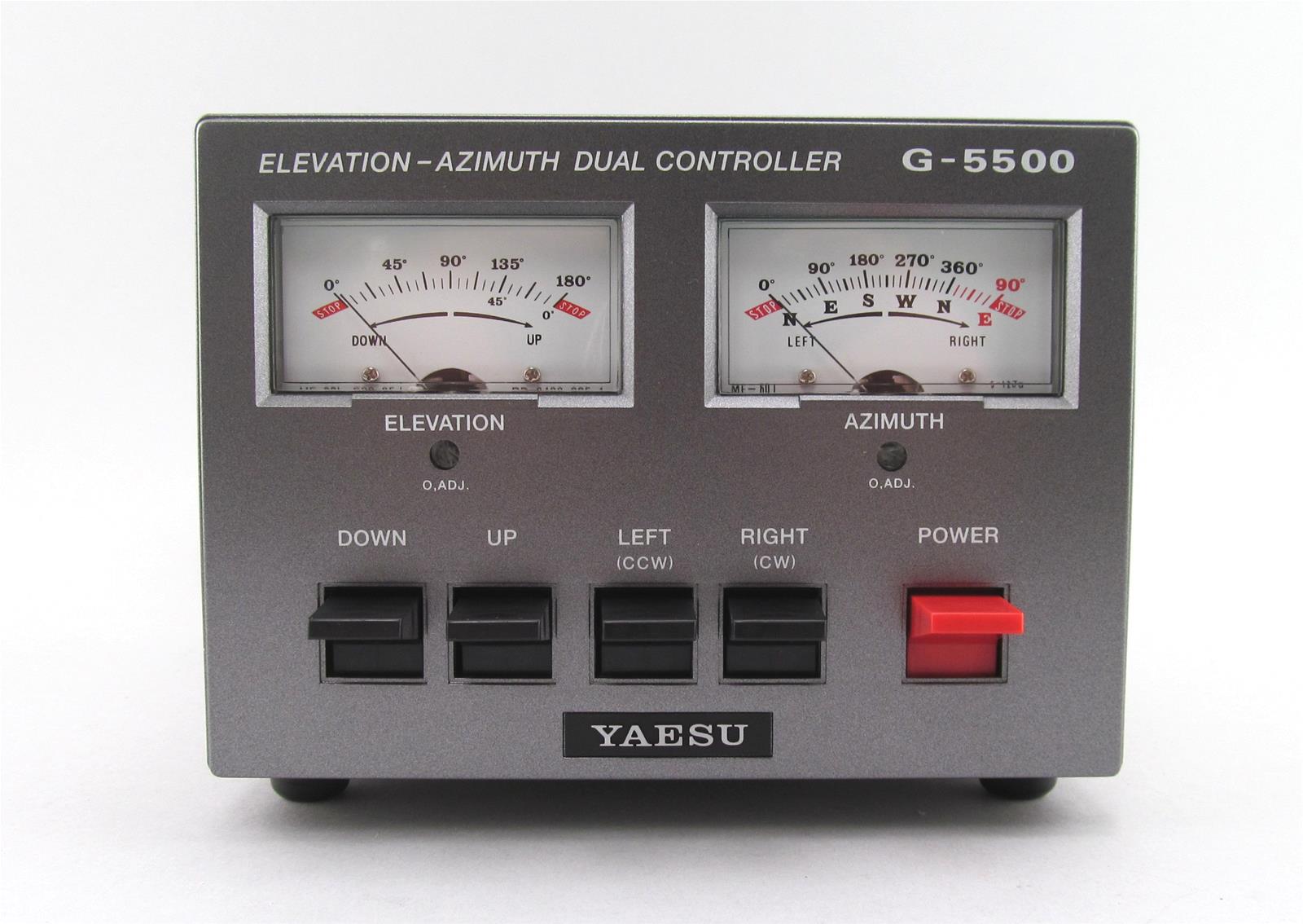
- Potentiometer feedback (the Yaesu G-5500): a multi-turn pot geared to the axis produces a voltage proportional to angle. Cheap and simple, but it drifts with temperature, has finite resolution, wears, and has no true wrap-around — it is “good enough” feedback that needs occasional calibration.
- Pulse / encoder feedback (Alfa-SPID, and DIY AS5600 builds): the controller counts pulses (incremental optical/Hall) or reads an absolute magnetic encoder. More repeatable and resolvable, but incremental encoders need a homing cycle on power-up to establish the reference, while absolute encoders (like the AS5600 magnetic chip) know their position immediately.
The mechanical load matters: the antenna’s wind load and any imbalance about the elevation axis are carried by the gear trains, so the array should be counter-balanced about the elevation axis and the mast/clamp/thrust-bearing sized for the wind load — the mast, bearing, and mounting mechanics are Vol 21. The control cable is a multi-conductor run carrying motor drive and feedback back to the controller box indoors; the controller’s protocols and the PC integration are Vol 34, but the rotator’s job ends at “accept a slew command, move, report position.”
33.6.2 DIY rotators
The SatNOGS rotator is the open-hardware reference design and the natural DIY choice. Born from the SatNOGS open ground-station network, its rotator (the v3 design and successors) is a 3D-printed gear-train az/el mount driven by stepper motors and a microcontroller, with published STLs, BOM, and firmware. It is sized for the light CP Yagi/helix arrays typical of cubesat and weather tracking, and because it speaks standard protocols it drops straight into the Vol 34 software stack. Expect a weekend of printing and a weekend of assembly; the parts cost is a few hundred dollars in steppers, bearings, fasteners, and filament.
A stepper + worm-gear + AS5600 magnetic encoder build is the from-scratch path: NEMA-17 or NEMA-23 steppers, worm-gear reductions (worm gears are self-locking, so the array holds position with the motor unpowered and resists wind back-drive), an AS5600 absolute magnetic encoder per axis (a $5 Hall-effect chip that reads 12-bit absolute angle off a diametric magnet on the shaft — no homing needed), and an Arduino/ESP32 running firmware that speaks GS-232 or EasyComm so tracking software can drive it. This is the most flexible DIY route and the one that teaches the most; the controller firmware (K3NG and the SatNOGS stack) is detailed in Vol 34.
Surplus-TV-rotator hacks are the cheapskate path: an old Channel Master / Alliance TV antenna rotator gives you the azimuth axis for nearly free, and a linear actuator (a satellite-dish “actuator arm” or a surplus 12 V linear actuator) bolted to tilt the boom gives a crude elevation axis. Add a couple of AS5600s or pots for feedback and a microcontroller, and you have a low-cost az/el good enough for forgiving wide-beam arrays. The compromises are slop, limited torque, and coarse resolution — fine for a broad helix, marginal for a narrow high-gain array.
33.6.3 Commercial buys — az/el rotators (mid-2026)
Table 7 — Commercial buys — az/el rotators (mid-2026)
| Tier | Model | Feedback | Capacity | Price | Notes |
|---|---|---|---|---|---|
| Entry (az-only fallback) | Yaesu G-450A / G-1000DXA + manual elevation | pot | light VHF/UHF | $250–500 | Az-only; works low passes / fixed-el setups only — not a real satellite solution |
| Canonical | Yaesu G-5500 / G-5500DC | pot, both axes | light-medium CP arrays | $700–800 | The reference amateur az/el; az 450°, el 180°; pairs with GS-232 interface (Vol 34) |
| Mid | Alfa-SPID RAS / RAS-HR | pulse | medium | $900–1300 | Pulse feedback, very repeatable; Rot2Prog controller |
| Premium | Alfa-SPID BIG-RAS / BIG-RAS-HR | pulse | large arrays | $1500–2200 | Heavy CP Yagi stacks; high resolution |
| Premium | M2 Antenna OR-2800PX (az) + MT-3000 (el) / LEO pack | pot/optical | large | $1500–2500+ | Pairs with M2’s RC2800 controller; the big-station choice |
What to avoid: trying to use a plain az-only beam rotator (Ham-IV, G-1000) as a satellite rotator — without an elevation axis it cannot track anything but the lowest passes, and bolting the array fixed-elevation throws away most passes. Also avoid undersizing: a rotator rated for a light HT-beam will strip its gears under a wind-loaded crossed-Yagi LEO pack. Match the rotator’s torque and wind-load rating to the actual array, with margin (Vol 21).
33.7 GEO and Starlink — a situating note
Two regimes sit at the edge of this volume’s scope and deserve placing rather than building.
Geostationary comms is the easy half. A geostationary satellite orbits at 35,786 km in the equatorial plane with a 24-hour period, so it appears fixed in the sky from any ground point — a single azimuth and elevation, aimed once and bolted down. This is exactly why QO-100 needs only a fixed dish and no rotator: point at the bird’s slot (for QO-100/Es’hail-2, 26° East, so a specific az/el for your location), peak it once, and you are done forever. Every broadcast-TV dish on every rooftop is the same idea. The hardware cost of “geostationary” is paid entirely in the link budget — 35,786 km is far, so the dish has to be big enough and the LNB quiet enough — and not at all in pointing machinery. Vol 34 works the QO-100 aiming as its “no-tracking” example.
Starlink sits conceptually outside the build-it world entirely, and it is worth understanding why. A Starlink user terminal tracks a constellation of fast-moving LEO satellites not with a rotator but with an electronically steered phased array — a flat panel of hundreds of patch elements whose relative phase is adjusted in real time to form and steer a beam with no moving parts, handing off from one satellite to the next as they cross. This is the same beam-forming principle as a phased vertical array (Vol 32) but at Ku-band with per-element electronic phase control, and it is a closed, proprietary appliance — not a build target, not a serviceable antenna in the sense of this series. It is included here only to situate it: when someone asks “why can’t I track LEO sats with a flat panel like Starlink does,” the answer is that you can in principle, but the phased-array beamformer that makes it work is a custom ASIC-and-RFIC system, whereas the amateur path to the same end is a CP Yagi on an az/el rotator.
33.8 Companion gear and integration
A satellite antenna is the front of a chain, and the chain’s weak links are usually behind the antenna, not in it.
Masthead preamp and sequencer. As established under the link budget, the LNA belongs at the antenna (Vol 19). On a transmit-capable station (any uplink), the masthead preamp must be protected from the transmitter’s power, which is the job of a sequencer: a small controller that, on transition to transmit, first bypasses/powers-down the preamp, then keys the PA, and on return to receive does the reverse — with deliberate millisecond delays so the preamp is never live into transmit power and the PA never keys into an unswitched relay. A preamp without sequencing on a TX antenna is a preamp with a short lifespan. For the full-duplex satellite case (transmit up on one band while receiving down on another, as on a V/U bird), the two bands are separate chains and the sequencing protects the downlink preamp from the uplink’s nearby radiation.
The QO-100 LNB chain. Recapping the dish section: bias-T to power the LNB up the coax (12–14 V), a reference-locked or Bullseye LNB so the LO does not drift the narrow signals, and the ~739 MHz IF down to the SDR. If you run SSB/CW on QO-100, the reference lock is not optional.
Feedline at each band. The satellite rule from the link-budget section, made concrete: keep the run short and the loss low, and put the gain ahead of the loss. At 2 m, decent coax (LMR-400) is fine. At 70 cm, LMR-400 minimum and keep it short. At 23 cm, LMR-400 is already lossy — masthead preamp mandatory. At 10 GHz there is no coax solution — the LNB downconverts at the feed and only the IF travels coax. See Vol 5 for the loss-per-100-ft-per-band tables.
Which hub radio pairs with which satellite antenna. The use-case matrix is Vol 29; the satellite-specific pairings:
Table 8 — Which hub radio pairs with which satellite antenna. The use-case matrix is [Vol 29](vol29.md); the satellite-specific pairings
| Radio | Best satellite use | Antenna |
|---|---|---|
| RTL-SDR | 137 MHz weather, QO-100 RX (via LNB IF), GOES L-band, Inmarsat | QFH (137), dish+LNB (QO-100/GOES), patch (L-band) |
| HackRF One | wideband RX across all of the above; QO-100 2.4 GHz uplink TX | dish/helix/patch as appropriate |
| UV-K5 | FM “easy sats” (SO-50, ISS, PO-101) | Arrow II / Elk handheld, walk-and-track |
| Airspy / SDRplay | GOES HRIT, sensitive L-band | dish + L-band LNA |
33.9 Common gotchas and myths
-
Wrong CP sense (RHCP vs LHCP) costs 20+ dB. This is the big one. A CP-to-CP path with mismatched sense is not “a little worse” — it is catastrophically worse, and it is invisible until you compare against the correct sense. If a CP antenna seems mysteriously deaf on a bird whose sense it should match, suspect that you built or wired the opposite sense. A switchable-sense feed (relay-flipped hybrid) sidesteps the whole class of error.
-
“9 dBi omni” is a physical impossibility. Gain is pattern concentration; an antenna that radiates equally in all directions has 0 dBi (less, with losses). A high gain figure on an “omnidirectional satellite antenna” listing means either the pattern is not actually omni (it has a narrow elevation beam) or the dBi number is fiction. For fixed all-sky coverage you want low gain spread over the whole dome (the QFH’s virtue), not a high number.
-
Feedline loss can eat the entire L-band link. A run of cheap coax that costs you 2 dB at 145 MHz can cost 8–10 dB at 1.7 GHz, which is the difference between decoding GOES and decoding noise. The masthead LNA and short, low-loss coax are not refinements at L-band; they are the whole game.
-
Preamp at the rig does almost nothing; preamp at the masthead does everything. Putting the LNA in the shack amplifies the signal and the feedline loss equally — system noise figure is set by the first stage and what precedes it, so an LNA behind a lossy run of coax cannot recover what the coax already threw away. The LNA must see the antenna’s signal first, at the masthead.
-
Axial ratio reality versus the spec. The quoted AR is on-boresight and best-case. Off-axis, a “1 dB AR” antenna can be 6–10 dB AR — i.e. nearly linear at the edges of its pattern. Do not assume a CP antenna is cleanly CP over its whole beam; the good-CP cone is narrower than the half-power beamwidth.
-
Ground reflections wreck a horizon pass. At low elevation the bird’s signal arrives both directly and via a ground bounce (which is polarization-flipped and delayed), producing deep nulls and multipath. This is why low passes are noisy and why horizon-favoring patterns (Lindenblad, eggbeater) and a little antenna height help — and why the strongest part of any pass is up high, away from the ground.
-
An az-only rotator is not a satellite rotator. Without elevation you can track only the lowest passes (the ones near the horizon where the bird stays at low elevation). Every high pass — the good ones — climbs out of an az-only rotator’s reach. Elevation is the whole point of an az/el.
-
The QFH/turnstile feedline radiates if you skip the choke. A CP fixed antenna with common-mode current on the outside of the downlead has a corrupted pattern and a wrecked axial ratio — the very properties you built it for. The choke balun at the feed is not optional on these designs.
33.10 Resources
- ARRL Satellite Handbook and the satellite chapter of the ARRL Antenna Book — the canonical amateur references for satellite antennas and ground-station design.
- AMSAT (amsat.org) — the Radio Amateur Satellite Corporation: bird status, frequency lists, the AMSAT antenna and ground-station notes, and the LEO-pack/eggbeater design heritage.
- QO-100 / Es’hail-2 community — BATC (British Amateur Television Club, batc.org.uk) and the AMSAT-DL QO-100 pages — the reference for dish/LNB/reference-lock practice on the geostationary transponder, including the QO-100 wideband and narrowband transponder details.
- SatNOGS (satnogs.org) — the open-source satellite ground-station network: the open-hardware az/el rotator design (STLs, BOM, firmware), the client/controller stack, and the observation database. The DIY rotator reference.
- John Coppens’ online QFH antenna calculator (jcoppens.com) — the community-standard quadrifilar-helix designer used in the DIY build above.
- Ed Fong (WB6IQN) and the G6LVB / Arrow lineage — the practical handheld and roll-up satellite-antenna designs; the Arrow II and Elk handhelds and their phasing/duplexer notes.
- Weather-satellite decoding community — the NOAA APT and Meteor-M LRPT scene (WXtoImg’s successors, SatDump, the r/RTLSDR and rtl-sdr.com guides), and the GOES HRIT projects (goestools, SatDump) for the L-band dish builds.
- DK7ZB and WA5VJB — published crossed-Yagi and “Cheap Yagi” satellite-array designs referenced in the DIY crossed-Yagi build.
- Companion volumes in this series: Vol 5 (feedline loss), Vol 11 (Yagi theory), Vol 16 (baluns/chokes), Vol 18 (power dividers/combiners), Vol 19 (masthead preamps/LNAs/bias-T), Vol 21 (masts/mounting/bearings), Vol 29 (radio↔antenna use-case matrix), Vol 30 (multi-radio shared antennas, the GPS exception), Vol 31 (regulatory and RF safety), and the companion Vol 34 — Satellite Tracking: Orbital Mechanics, Coordinates & Control — for where the az/el numbers come from and the three paths (PC, DIY, COTS) to drive the rotator covered here.