Satellite Antennas & Rotators · Volume 5
Az/El Rotators: Sizing, Building and Buying
The zenith keyhole computed to a threshold instead of a shrug, the two torque figures that decide whether a rotator survives, and a market whose reference product is a third more expensive than the chapter says
5.1 About this volume
A tracked array needs to move in two axes, and elevation is the axis that makes a satellite rotator a different machine from a beam rotator. Vol 3 established what the tracking buys — 6 to 10 dB over a fixed antenna — and this volume is about the machinery that collects it, considered as a mechanism: its gear trains, its position feedback, the torque it must produce and the torque it must survive.
Three results in this volume differ from the seed chapter, and all three come from putting numbers on statements it makes qualitatively.
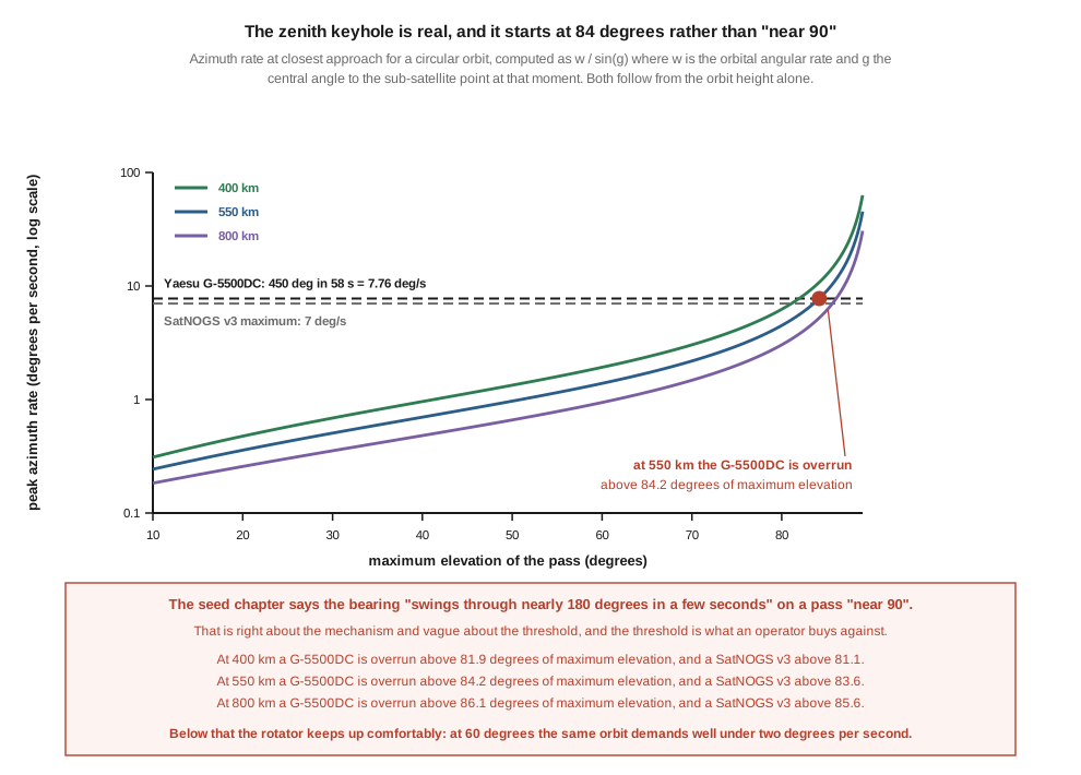
The zenith keyhole has a threshold, and it is not “near 90 degrees”. §4 computes the azimuth rate a pass demands from the orbit geometry. On a 550 km orbit a Yaesu G-5500DC is overrun above 84.18 degrees of maximum elevation, a SatNOGS v3 above 83.55, and at 400 km those fall to 81.93 and 81.07. Below the threshold the rotator keeps up easily — a 60-degree pass demands 1.39 degrees per second against the Yaesu’s 7.76.
And the keyhole costs about one pass in forty. §5 computes the pass statistics from the same geometry: 2.55 % of visible passes at 550 km climb above the G-5500DC’s threshold. That is what turns the keyhole from a frightening phrase into a specification to check before buying.
Sizing needs two torque figures, not one, and the seed chapter’s advice cannot be acted on without them. §6 computes the wind loading. The M2 LEO Pack’s published wind areas make 276 in-lb at 50 mph on a 48-inch offset and 1,106 in-lb at 100 mph, against the G-5500DC’s 428 in-lb of turning torque and 2,604 in-lb of brake. Those two ratings answer two different questions — turning torque is sized by the wind the rotator must move in, brake torque by the wind it must hold in — and conflating them is how an undersized rotator gets bought.
🔴 The market has moved too. §9: the reference amateur az/el rotator is $969.99, where the seed chapter says $700–800.
5.2 What an az/el rotator is, mechanically
An az/el rotator is two independent gear trains stacked. The azimuth unit sits on the mast and rotates the whole assembly in the horizontal plane. Above it the elevation unit tilts the antenna boom from the horizon upward. Each axis has its own motor, its own reduction, and — the part that distinguishes a rotator from a motor — its own position feedback, because the controller has to know where the array points rather than merely command it.
Three mechanical figures characterise any of them, and only the first is usually quoted in a conversation.
Rotation range. The reference amateur unit gives 450 degrees in azimuth and 180 in elevation. The azimuth overlap of 90 degrees exists so that a pass crossing north does not have to unwind through a full rotation, and the 180 degrees of elevation exists so that the array can be tipped past the zenith and pointed down the other side — which is the mechanical half of the keyhole mitigation §4 discusses.
Slew rate. Roughly one minute for a full azimuth rotation, which on a 450-degree range is 7.76 degrees per second. §4 is entirely about this number, and it is the one specification a satellite rotator has that a beam rotator does not need.
Torque, in two figures. Turning torque is what the motor can produce against a load; brake torque is what the stationary mechanism can resist. For the reference unit those are 428 and 2,604 inch-pounds — a ratio of six to one. §6 shows why both are needed and what each is sized against.
The control cable is a multi-conductor run carrying motor drive and feedback to a controller box indoors. The rotator’s job ends at “accept a slew command, move, report position.” What produces the slew command is the companion dive’s subject; §10 states the boundary.
5.3 Position feedback, and the two families
The controller must know where the array is. Two families dominate, and the seed chapter characterises both correctly; what follows adds the consequence each has for a satellite station specifically.
Potentiometer feedback, as in the Yaesu G-5500: a multi-turn potentiometer geared to the axis produces a voltage proportional to angle. It is cheap, simple, and absolute — at power-up the controller already knows the position, with no reference procedure. Against that it drifts with temperature, has finite resolution, wears at the wiper, and needs periodic calibration against a known bearing.
⭐ The satellite-specific consequence is that pot drift and beamwidth interact, and it decides how much the drift matters. Vol 3 §8 computed a ten-turn helix at 34 degrees of half-power beamwidth, and M2’s published crossed-Yagi beamwidths are 60 degrees on 2 m and 42 on 70 cm. A degree or two of feedback error against a 42-degree beam is nothing. The same error against Vol 4 §3’s 10 GHz dish — 2.00 degrees wide at one metre — is the whole beam. Feedback quality is a specification of the antenna as much as of the rotator, and a station that would be perfectly served by a potentiometer at 70 cm needs something better at 10 GHz. That said, a 10 GHz geostationary dish is not on a rotator at all, so in practice the potentiometer is adequate for nearly every tracked amateur array.
Pulse and encoder feedback, as in the Alfa-SPID units and in home-built designs: the controller counts pulses from an incremental sensor, or reads an absolute one. It is more repeatable and more finely resolved. The distinction within the family matters: an incremental encoder counts changes and therefore needs a homing cycle at power-up to establish its reference, while an absolute encoder — the AS5600 magnetic type reads a 12-bit angle from a diametric magnet on the shaft — knows its position immediately, like a potentiometer, but without the drift.
⚠ For an unattended station that is the deciding property rather than resolution. A rotator that loses power in a storm and comes back needing a homing cycle it cannot perform unsupervised is a rotator that has stopped working until someone visits it.
5.4 The zenith keyhole, computed
The seed chapter describes the keyhole this way: “on a pass that culminates near 90° elevation, the azimuth bearing swings through nearly 180° in a few seconds right at the top of the arc. No conventional az rotator slews that fast.”
That is right about the mechanism and vague about the threshold, and the threshold is the part an operator buys against.
The geometry is straightforward. At closest approach the sub-satellite point is moving at the orbital angular rate ω, perpendicular to the line joining it to the observer, at a central-angle distance g₀. The observed bearing therefore sweeps at
dAz/dt = ω / sin(g₀)
and g₀ follows from the maximum elevation and the orbit height. As the pass gets higher, g₀ goes to zero and the rate diverges — the keyhole is a 1/sin singularity, which is why it appears so abruptly.
Evaluated for a 550 km circular orbit:
Table 1 — Evaluated for a 550 km circular orbit
| maximum elevation | peak azimuth rate |
|---|---|
| 20° | 0.36 °/s |
| 40° | 0.70 °/s |
| 60° | 1.39 °/s |
| 75° | 2.96 °/s |
| 84° | 7.53 °/s |
| 85° | 9.04 °/s |
| 88° | 22.64 °/s |
Against that, the hardware. A G-5500DC covering 450 degrees in about 58 seconds delivers 7.76 °/s; a SatNOGS v3 is published at 7 °/s. Solving for where each is overrun:
Table 2 — Against that, the hardware. A G-5500DC covering 450 degrees in about 58 seconds delivers 7.76 °/s; a SatNOGS v3 is published at 7 °/s. Solving for where each is overrun
| orbit height | G-5500DC overrun above | SatNOGS v3 overrun above |
|---|---|---|
| 400 km | 81.93° | 81.07° |
| 550 km | 84.18° | 83.55° |
| 800 km | 86.06° | 85.64° |
⭐ Two things fall out that the qualitative account does not give.
The threshold is a little over 84 degrees, not “near 90”. A pass to 85 degrees already demands more than the reference rotator can deliver, and one to 88 demands three times as much. Conversely, everything up to about 80 degrees is comfortable with margin to spare — at 60 degrees the rotator is loafing at under a fifth of its rate.
And the threshold falls as the orbit gets lower. A 400 km orbit — the ISS region — is overrun above 81.9 degrees, where an 800 km weather orbit is safe to 86.1. Lower satellites move faster in angular terms and pass closer, so the keyhole is worse for the birds that are otherwise easiest.
⚠ One mechanical clarification, because the seed chapter’s phrasing invites a wrong inference. “No conventional az rotator slews that fast” is true, but the reason a station copes anyway is not that the rotator catches up. It is that the array has a beamwidth: Vol 3’s 42-degree 70 cm crossed Yagi can be pointing 20 degrees off and still be within its half-power beam. The keyhole costs a few seconds of degraded pointing at the top of the arc, not a lost pass — and it costs nothing at all to a fixed antenna, which is Vol 2 §2’s point.
5.5 How often it actually matters
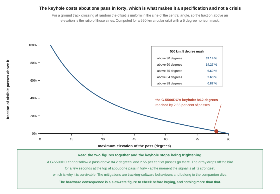
A threshold is only half a specification; the other half is how often it is crossed.
For a ground track crossing the observer’s visibility circle at a random offset, the offset is uniform in the sine of the central angle, so the fraction of passes exceeding a given maximum elevation is the ratio of those sines. For a 550 km orbit with a 5-degree horizon mask:
Table 3 — For a ground track crossing the observer's visibility circle at a random offset, the offset is uniform in the sine of the central angle, so the fraction of passes exceeding a given maximum elevation is the ratio of those sines. For a 550 km orbit with a 5-degree horizon mask
| maximum elevation exceeds | fraction of visible passes |
|---|---|
| 30° | 39.14 % |
| 60° | 14.27 % |
| 75° | 6.69 % |
| 84.18° (the G-5500DC’s keyhole) | 2.55 % |
| 88° | 0.87 % |
⭐ So the keyhole affects about one pass in forty, for a few seconds, at the moment the signal is strongest. That is the whole of its practical cost, and stating it numerically changes how it should be weighed: it is a specification worth checking before buying a rotator and it is not a reason to choose a different architecture.
⭐ The same table has a second use, and it is the more valuable one. It says that 39 % of passes never exceed 30 degrees and that only 6.7 % exceed 75. A station’s typical pass is a low one, which is exactly where Vol 1 §8’s budget is worst — longest slant range — and where Vol 1 §6 said a fixed antenna’s axial ratio is poorest. The passes an operator actually gets are the hard ones, and a station optimised for the spectacular overhead pass has optimised for 2 % of its traffic. That argues for low-elevation performance — horizon-favouring patterns, a clear horizon, a mast that is high rather than an array that is large — over peak gain.
⚠ These figures assume a randomly-placed ground track and a clear horizon to 5 degrees. A real station with trees or buildings on one side sees fewer usable passes and a distribution skewed further toward high elevations, because the low ones are the first to be blocked.
5.6 Sizing: the two torque figures
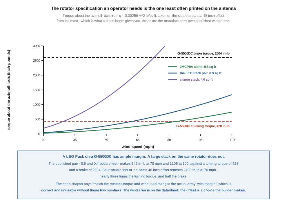
The seed chapter’s advice is: “Match the rotator’s torque and wind-load rating to the actual array, with margin.” That is correct and cannot be acted on, because it gives neither the antenna’s number nor the rotator’s.
Both are published. US practice takes the dynamic pressure of wind as q = 0.00256 · V² pounds per square foot with V in miles per hour, so the torque about the azimuth axis is q × A × r, with A the antenna’s wind area and r its offset from the mast — which for a cross-boom is a real lever arm of several feet.
Taking the M2 wind areas Vol 3 §11 verified — 0.5 sq ft for the 2MCP8A, 0.4 for the 436CP16 — at a 48-inch offset:
Table 4 — Taking the M2 wind areas [Vol 3](/satellite-antennas-rotators/vol-3/) §11 verified — 0.5 sq ft for the 2MCP8A, 0.4 for the 436CP16 — at a 48-inch offset
| wind area | 50 mph | 70 mph | 90 mph | 100 mph |
|---|---|---|---|---|
| 0.5 sq ft (one 2 m crossed Yagi) | 154 in-lb | 301 | 498 | 614 |
| 0.9 sq ft (the LEO Pack pair) | 276 in-lb | 542 | 896 | 1,106 |
| 4.0 sq ft (a large crossed stack) | 1,229 in-lb | 2,408 | 3,981 | 4,915 |
Against the G-5500DC’s 428 in-lb turning and 2,604 in-lb brake.
⭐ The two ratings answer two different questions, and this is the distinction the seed chapter’s single sentence collapses.
Turning torque is sized by the wind the rotator must move in, which is an operating condition — nobody tracks a satellite in a 90 mph gale. At a realistic 30 mph operating wind the LEO Pack pair at a 48-inch offset needs about 100 in-lb, comfortably inside 428. Even at 50 mph it needs 276, still inside.
Brake torque is sized by the wind the rotator must survive, stationary, unpowered, with the array left wherever the last pass finished. That is a survival condition, and the relevant figure is the local design wind. The LEO Pack pair at 100 mph makes 1,106 in-lb against a 2,604 in-lb brake — a margin of 2.4 to one.
So the reference rotator is correctly sized for the reference array, with real margin on both counts, and the large crossed stack is not: 4 sq ft at 70 mph already produces 2,408 in-lb, which is 93 % of the brake rating and nearly six times the turning torque. That array wants a bigger rotator, and it is the case the seed’s warning against undersizing is really about.
⚠ Two things this calculation does not include, and both make it optimistic. It takes only the azimuth axis, whereas the elevation axis sees the same force at whatever arm the boom’s centre of pressure sits at. And it uses a flat drag coefficient implied by the manufacturer’s stated wind area, where a real array in a gust sees dynamic and torsional loads that a steady-state figure does not capture. The published wind area is the right input available; it is not a structural analysis.
⭐ The most useful consequence for a buyer is about the mounting rather than the rotator. Torque is linear in the offset. Halving the distance from the mast to the array’s centre of pressure halves the torque, at no cost. A cross-boom that puts the antennas closer in is worth as much as a larger rotator, and it is free — which is not a trade the antenna listings will ever suggest.
5.7 Counterbalance, and why the elevation axis is the fragile one
The seed chapter says the array “should be counter-balanced about the elevation axis”. That is right and it is worth saying why, because the reason is not the one most builders assume.
An unbalanced array puts a static moment on the elevation gear train, all the time, in one direction. It is not the peak load that matters — a gearbox will take a static moment — it is that the load never reverses. Backlash is taken up on one flank permanently, wear concentrates on one side of the tooth, and the motor works against gravity on the way up and is driven by it on the way down. The second of those is the dangerous one: a gear train back-driven by an overhauling load is a gear train that can run away, and the elevation axis is the one where gravity is always available to do it.
Counterbalancing removes the static moment, so the load reverses through zero as the array tips, wear distributes, and the drive is never overhauled.
⭐ The satellite-specific aggravation is that a satellite array is asymmetric by construction. A terrestrial beam sits on its mast at the balance point of a single boom. A satellite array has a 2 m Yagi on one side of a cross-boom, a 70 cm Yagi on the other, and usually a masthead preamplifier, a relay box and a cable loom concentrated at one end. Vol 3 §11’s published weights are 4 lb each for the two M2 antennas, which balance each other; the preamplifier, the coax and the hardware do not.
And the elevation axis is the one that carries the whole weight of the array at its worst angle, at 0 and 180 degrees, where the boom is horizontal and the moment is greatest. That is where the array sits between passes.
5.8 DIY — SatNOGS, and the from-scratch path
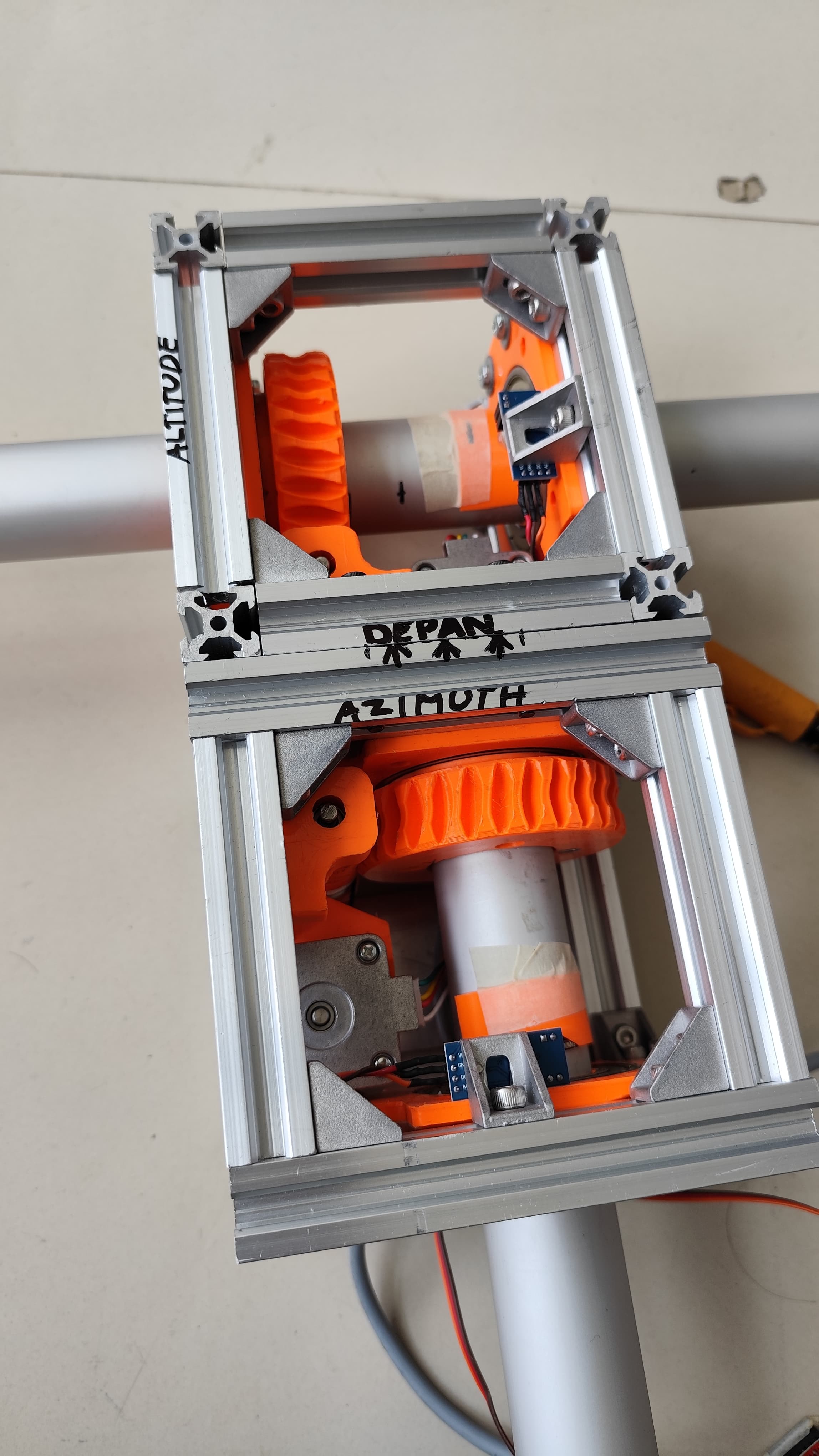
The SatNOGS rotator is the open-hardware reference design and the natural DIY choice. Born from the open ground-station network, the v3 design is an aluminium-extrusion and 3D-printed az/el mount with published mechanical files, bill of materials and firmware. The published specification:
Table 5 — The SatNOGS rotator is the open-hardware reference design and the natural DIY choice. Born from the open ground-station network, the v3 design is an aluminium-extrusion and 3D-printed az/el mount with published mechanical files, bill of materials and firmware. The published specification
| SatNOGS v3 | Yaesu G-5500DC | |
|---|---|---|
| motors | 2 × NEMA 17 stepper, or DC | AC/DC gearmotors |
| reduction | worm gearbox, 30:1 | gear train |
| feedback | rotary encoders on the axes | potentiometer |
| accuracy | better than 1 degree | calibration-dependent |
| maximum rate | 7 °/s | 7.76 °/s |
| torque | about 30 N·m (≈ 266 in-lb) | 428 in-lb turning |
| cost | $300–400 in parts | $969.99 |
⭐ Read against §4 and §6, the comparison is closer than the price difference suggests. Its 7 °/s puts its keyhole at 83.55 degrees against the Yaesu’s 84.18 — a difference of two thirds of a degree, which §5’s table prices at under half a per cent of passes. Its 266 in-lb of torque is 62 % of the Yaesu’s, which §6 shows is still ample for a LEO-Pack-sized array at any operating wind.
⭐ And the worm gear changes the brake question rather than answering it. A worm drive with a sufficiently low lead angle is self-locking: the array holds position with the motors unpowered and resists wind back-drive without a brake at all. That is a genuine architectural advantage over a rotator that relies on a separate brake, and the seed chapter is right to flag it. ⚠ What cannot be stated here is the equivalent brake figure, because a self-locking worm’s holding capacity depends on the gear’s material and finish, and a printed gear is not a machined one. No published holding-torque figure for the printed drive was found for this dive, and §6’s survival-wind calculation therefore cannot be completed for a SatNOGS rotator. That is a real gap for anyone siting one where it will see high winds.
The from-scratch path — steppers, a worm reduction, an AS5600 absolute magnetic encoder per axis and a microcontroller — is the most flexible route and teaches the most. §3’s point applies: choose an absolute encoder so that the machine recovers from a power failure without a homing cycle.
Surplus television rotator conversions give the azimuth axis nearly free, with a linear actuator for elevation. ⚠ They are worth judging against §4 and §6 rather than dismissing: a TV rotator’s slew rate is typically far below 7 °/s, which by §4’s table pushes its keyhole down toward 70 degrees and, by §5’s, costs perhaps 8–10 % of passes rather than 2.5 %. For a broad-beam helix that is a reasonable trade at the price. For a narrow array it is not, and the compromises the seed chapter names — slop, limited torque, coarse resolution — are all real.
5.9 Buys, dated
Everything here was checked on 17 September 2026. Figures that could not be verified are marked as such rather than filled in.
5.9.1 Verified
Table 6 — Verified
| product | specification | price |
|---|---|---|
| Yaesu G-5500DC | az 450°, el 180°, turning torque 428 in-lb, brake 2,604 in-lb, wind load 5.4 sq ft mast-mounted or 10.8 sq ft inside a tower, about one minute per rotation | $969.99 |
🔴 The seed chapter prices the reference rotator at $700–800. It is $969.99 — 21 to 39 per cent low. That is the same class of error the antenna-tuners dive found across an entire product table, and it is the reason this program dates its price sections.
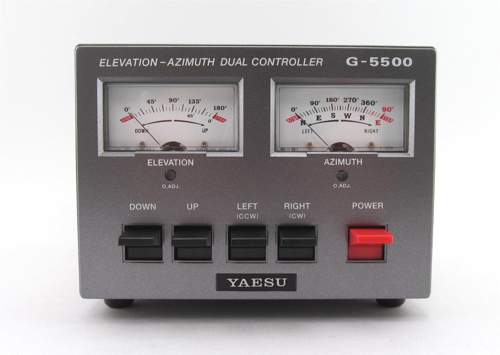
✅ Two of the seed’s figures for this rotator are confirmed, and one of them is confirmed by a photograph rather than by a datasheet: the controller’s own meters (§2) are scaled 0–180 degrees in elevation and 0–450 in azimuth.
⚠ The wind-load rating deserves one note, because it is easy to misread. 5.4 sq ft mast-mounted against 10.8 sq ft inside a tower is not a statement about the rotator’s gears; it is a statement about the bending moment the installation puts on it. The same rotator carries twice the antenna when a tower and thrust bearing take the side load. §6’s torque calculation is unaffected — it concerns the rotational axis — but a builder reading only the square-foot figure will get the wrong answer about mounting.
5.9.2 Unverified, and recorded as such
🔴 None of the seed chapter’s other five rotator rows could be verified, and they are not repeated as current figures.
- Alfa-SPID RAS / RAS-HR (“$900–1300”) and BIG-RAS / BIG-RAS-HR (“$1500–2200”). The manufacturer’s own sites could not be reached on 17 September 2026 (one presented a certificate that did not match its hostname, another refused the connection). ⚠ A check of a major distributor found no SPID rotator in its catalogue at all — only an AALogic DTC-100 controller described as compatible with AlfaSPID. That is a distribution observation and not a discontinuation notice; the distinction matters and the seed’s prices remain unchecked either way.
- M2 OR-2800PX plus MT-3000 (“$1500–2500+”). Not checked.
- Yaesu G-450A / G-1000DXA with manual elevation (“$250–500”). Not checked. ✅ The seed’s judgement on this row is confirmed below.
⚠ MFJ Enterprises stopped manufacturing on 17 May 2024, and sold rotator accessories, so the point applies here as it did in Vol 2 §11. Its web shop was live on 17 September 2026 and lists rotators and controllers. That is remaining stock, not production.
5.9.3 What to avoid, both of which survive
The seed chapter’s two warnings hold, and this volume has supplied the arithmetic behind both:
- “Trying to use a plain az-only beam rotator as a satellite rotator.” ✅ Confirmed, and §5 puts a number on it. Without an elevation axis the array is fixed at whatever elevation it was bolted at, and 39 % of passes never exceed 30 degrees while 61 % do — so a fixed-elevation installation is choosing which majority of its passes to lose, whichever angle it picks.
- “Undersizing: a rotator rated for a light HT-beam will strip its gears under a wind-loaded crossed-Yagi LEO pack.” ✅ Confirmed, and §6 makes it checkable. The published wind area and the offset give the torque; the rotator’s two published torque figures give the margin. Both numbers are on the respective datasheets, and neither is on the listing page of either product.
To those, §6 adds a third the seed does not have: buying a bigger rotator to solve a problem that a shorter cross-boom solves for nothing. Torque is linear in the offset, so the cheapest decibel of mechanical margin is a foot of lever arm removed.
5.10 Where this dive stops, and what it owes
5.10.1 The boundary, restated
Vol 1 §9 set it and this volume is where it bites hardest, so it is worth restating at the point of contact. This dive owns the rotator as a mechanism — gear trains, feedback sensors, slew rate, torque, wind load, counterbalance, and how to size and buy one. The companion dive at /satellite-tracking/ owns everything that decides where to point it: the orbital mechanics, the propagation of a two-line element set, the transformation to a look angle, the tracking programs, the controller protocols and the control software.
The keyhole is the clean example of the split. §4 computes the azimuth rate a pass demands and compares it against what rotators deliver, because that is a specification an operator buys against. The mitigations are not here: flipping the elevation axis past 90 degrees so azimuth can stay put, and leading or lagging azimuth through the turn, are behaviours of tracking software, and they belong to the companion dive along with the protocols that carry them.
5.10.2 What this dive owes
- No measurement in these five volumes is first-hand. Every figure is computed from a stated formula or read from a published specification. The two that most want a bench are Vol 2 §9’s and Vol 3 §10’s sense-and-axial-ratio checks, and neither has a procedure in this dive that uses equipment an amateur has.
- 🔴 Verifying the circular sense of a home-built antenna got harder in August 2025. Vol 2 §8: the seed’s check relied on watching NOAA APT passes peak, and there are no APT passes. The two substitutes offered are weaker and are said to be weaker. A procedure for measuring axial ratio and sense against a rotating linear source at a known distance is the single most useful thing this dive does not have.
- Photographs are owed for the handheld beams. Vol 3 §5: the seed’s photograph could not be confirmed to be the antenna it named, no Commons substitute exists, and the volume carries a diagram instead.
- Three questions are recorded as unresolved rather than decided: the axial-mode helix’s optimum pitch angle, where two reputable sources disagree and do not overlap (Vol 3 §8); the magnitude by which the Kraus gain expression overstates a real helix, which is well attested in direction and was not verified in size (Vol 3 §7); and the turnstile reflector spacing, where 0.25 λ and 0.3 λ are both in circulation (Vol 2 §4).
- The commercial sections are thin on purpose. Of roughly twenty product rows in the seed chapter, six were verified, and the rest are withdrawn or flagged rather than refreshed with fresh-looking numbers. ⚠ A withdrawn row is not a claim that the product does not exist — it is a statement that this dive could not confirm it on 17 September 2026.
- No volume in this dive has had an independent accuracy review. Author and checker have been the same throughout, which every previous dive in this program has found to be the weakest link.
- The SatNOGS holding-torque gap, §8: without a published figure for the printed worm drive, §6’s survival-wind calculation cannot be completed for the DIY rotator.
5.10.3 The dive in one paragraph
A satellite link breaks three assumptions at once, and each one costs hardware. The polarization wanders, so the antennas are circular — for a reason that is overwhelming at 2 m, strong at 70 cm, and essentially absent at 10 GHz. The link is power-starved, so the first amplifier goes at the antenna, where it recovers the feedline loss on top of the 5.4 dB any amplifier buys. And the target moves, so either the antenna floods the whole sky at a gain that cannot exceed 3.01 dBi, or it is pointed by a machine whose two torque ratings and one slew rate are all published and are all worth checking. The corrections in these five volumes were, as usual in this program, the product: a phasing line that was never a transformer, a helix formula printed with the wrong constant and then contradicted, a quadrifilar helix specified three incompatible ways, a dish dismissed as useless that has 14.8 dBi, a preamplifier position argued from a false premise to a correct conclusion, and a weather-satellite service that ended while the chapter recommending antennas for it was on the shelf.
5.11 Resources
- Yaesu G-5500DC specification and price — read from a major distributor’s product page on 17 September 2026. The az/el ranges are independently corroborated by the controller’s own meter scales in §2’s photograph.
- SatNOGS (satnogs.org, wiki.satnogs.org) — the open-hardware rotator: mechanical files, bill of materials, firmware, and the v3 specifications in §8, read 17 September 2026.
- The orbital geometry in §4 and §5 is computed from a circular two-body orbit and a spherical Earth. Both are approximations; neither affects the conclusions at the precision quoted.
- The wind loading in §6 uses the US convention
q = 0.00256 V²lb/sq ft, with the antennas’ own published wind areas from Vol 3 §11. - Vol 3 — the arrays this rotator carries, and the published wind areas §6 sizes from.
- Vol 4 — the 10 GHz dish whose 2-degree beam makes §3’s feedback discussion matter.
- Vol 2 — the antennas that make this whole volume optional.
- Mounting, masts and physical installation — the mast, thrust bearing and tower that carry the side load §9 distinguishes from the torque.
- Satellite tracking — where the azimuth and elevation numbers come from, the controller protocols, and the keyhole mitigations §10 hands off.
Comments (0)